
Views: 0 Author: Site Editor Publish Time: 2026-07-21 Origin: Site


The continuous casting process operates as the primary pacing mechanism in modern steel production. The alignment between melt shop output and casting throughput dictates overall plant profitability. If your continuous caster runs too slow, liquid steel remains stranded in ladles, leading to thermal degradation and severe scheduling bottlenecks on the floor. Conversely, an oversized caster results in underutilized capital, excessive maintenance overhead, and inefficient energy consumption.
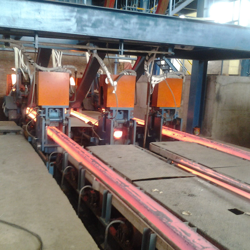
Evaluating true continuous caster capacity requires moving beyond theoretical tonnage. Plant engineers and procurement teams must analyze the mechanical, metallurgical, and operational variables that govern throughput. By understanding the constraints of heat extraction, metallurgical length, and sequence casting efficiency, steelmakers can accurately size equipment to match upstream furnace pacing and downstream rolling mill demands.
Throughput Equation: Continuous caster capacity is fundamentally governed by the cross-sectional area of the product, casting speed, steel density, and the number of cast strands.
Metallurgical Limits: Maximum casting speed is strictly constrained by heat extraction rates in the mold and the required metallurgical length for complete solidification.
Technology & Design Impact: Traditional strand casters scale capacity through multi-strand configurations, whereas specialized twin-belt continuous casting technologies achieve high-velocity throughput (up to 14 m/min) for specific sheet or strip geometries.
Operational Yield: Achieving up to 98% yield requires optimizing sequence casting and minimizing ladle turnaround times, rather than simply increasing machine speed.
Procurement Framework: Selecting a steel mill continuous caster requires balancing capital expenditure against the specific grade mix, desired cross-sections, and existing upstream furnace pacing.
Table of Contents
The standard capacity formula provides the baseline for evaluating throughput on the melt shop floor. Capacity measured in tons per hour equals the cross-sectional area multiplied by the casting speed, the density of the steel, the number of strands, and a utilization factor. This equation highlights that increasing any single variable directly impacts the total output. However, physical and metallurgical limits restrict how high casting speed or cross-sectional area can go before internal quality degrades or breakouts occur.
To break this down practically, operators look at the specific inputs that drive the daily tonnage. Each variable requires precise control and monitoring through the plant's Level 2 automation system.
Variable | Definition | Operational Impact |
|---|---|---|
Cross-Sectional Area | The width and thickness of the mold (e.g., 150x150mm billet or 1000x200mm slab). | Determines the volume of steel cast per meter. Larger areas require slower speeds to solidify. |
Casting Speed | The rate at which the strand is withdrawn from the mold (meters per minute). | Directly drives throughput but is limited by the machine's metallurgical length and cooling capacity. |
Steel Density | The specific weight of the liquid steel, typically around 7.8 tons per cubic meter. | A fixed constant based on the alloy composition, used to convert volume into tonnage. |
Number of Strands | The total parallel casting lines fed by a single tundish. | Multiplies total output. Billet casters often use 4-8 strands; slab casters use 1-2. |
Utilization Factor | The percentage of time the machine is actively casting versus downtime. | Driven by sequence casting success, maintenance schedules, and turnaround times. |
A high-speed machine only delivers value if it synchronizes with the upstream melt shop. The caster's consumption rate must align with the tapping cycle and total capacity of the Basic Oxygen Furnace (BOF) or Electric Arc Furnace (EAF). If the caster consumes steel slower than the furnace produces it, ladles queue up on the turret. This queue time causes temperature drops, requiring secondary heating at the Ladle Metallurgy Furnace (LMF) or risking premature solidification in the slide gate.
Consider a plant operating a 120-ton EAF with a tap-to-tap time of 60 minutes. The continuous caster must consume exactly 120 tons per hour to maintain equilibrium. If the continuous caster capacity is only 100 tons per hour, the melt shop must slow down furnace operations, wasting energy and reducing overall plant yield. Conversely, if the caster can pull 150 tons per hour, it will drain the tundish before the next heat is ready, breaking the continuous sequence and forcing a machine restart.
Precise capacity calculations prevent bottlenecking at the ladle refining station. When the caster matches the melt shop pace, it ensures a continuous feed to downstream hot rolling mills. This synchronization minimizes energy loss. Hot billets or slabs can transfer directly to reheat furnaces or rolling stands while still retaining core heat. This practice, known as hot charging, drastically reduces natural gas consumption in the reheat furnace and improves overall plant thermal efficiency.
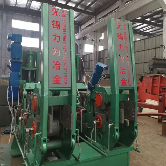
The number of cast strands heavily influences total capacity and dictates the physical footprint of the casting deck. Single-strand slab casters typically handle large cross-sections for flat products, pulling massive volumes of steel through a single, wide mold. In contrast, billet and bloom casters utilize multi-strand configurations, often running 4 to 8 strands simultaneously. Multiple strands multiply the throughput without requiring unmanageable casting speeds.
This approach introduces specific mechanical trade-offs. Higher strand counts require complex delta-shaped tundish designs to ensure uniform flow control, consistent residence time, and even temperature distribution across all strands. Maintenance complexity scales linearly with the number of strands. Each line requires its own copper mold, hydraulic oscillator, withdrawal straightener, and independent secondary cooling zones.
The machine radius dictates the metallurgical length, defined as the physical distance from the meniscus in the mold to the point of complete solidification deep in the containment segments. A longer metallurgical length supports higher casting speeds. As the strand moves through the machine, the solid shell grows inward. The liquid core must completely solidify before the strand reaches the unbending rollers.
If the machine runs too fast for its designed length, the steel retains an unsolidified liquid core when it hits the unbending point. Bending or unbending a strand with a liquid core causes severe internal cracking, known as halfway cracks, and creates a high risk of a breakout. Therefore, the physical dimensions of the bow—whether it is a 7-meter radius for billets or a 10-meter radius for thick slabs—strictly cap the maximum safe casting speed.
The continuous casting process involves pouring melted metal through an open-ended copper mold to initiate the solid shell. The mold acts as the primary heat extraction zone. High-velocity water cooling channels machined directly into the copper plates rapidly pull heat from the liquid steel, forming a solid outer skin. The rate of primary heat extraction limits the maximum speed at which metal can exit the mold.
If the withdrawal speed exceeds the mold's cooling capacity, the shell remains too thin to withstand the ferrostatic pressure of the liquid core. This results in a breakout just below the mold exit. To maximize heat transfer, operators utilize mold oscillation. The mold rapidly moves up and down, creating a negative strip time that heals surface tears and drives mold powder down the mold walls for lubrication.
Traditional vertical-curved multi-strand casters dominate the production of billets, blooms, and thick slabs. These machines rely on gravity and curved containment segments equipped with hundreds of rollers to guide the steel. In contrast, twin-belt continuous casting architectures utilize parallel moving steel belts to form the mold cavity itself.
Feature | Conventional Strand Caster | Twin-Belt Caster |
|---|---|---|
Mold Type | Stationary oscillating copper tube or plates. | Moving parallel steel belts with water film cooling. |
Typical Products | Billets, blooms, thick slabs, round bars. | Thin slabs, aluminum strip, specialized steel sheets. |
Casting Speed | 1 to 5 meters per minute. | Up to 14 meters per minute. |
Orientation | Vertical-curved or straight with bending. | Near-horizontal or slight incline. |
Primary Advantage | High volume production of standard structural shapes. | Near-net-shape casting, eliminating roughing mill passes. |
Twin-belt setups achieve rapid casting speeds, reaching up to 14 meters per minute. They deliver rates up to 60 tons per hour for near-net-shape outputs. Twin-belt systems excel at producing thin slabs or specialized strip geometries, whereas conventional strand casters handle massive volumes of standard structural cross-sections.
Below the mold, the strand enters the secondary cooling zone, which is divided into multiple segments. Here, water sprays and air-mist nozzles extract the remaining heat to complete solidification. Aggressive cooling increases continuous caster capacity by shortening the required metallurgical length, allowing operators to increase the withdrawal speed.
Operators face a strict trade-off between speed and quality. Excessive cooling induces severe thermal stresses. If the surface cools too rapidly while the core remains hot, the temperature gradient causes internal cracks, surface defects, or shape distortion (such as rhomboidity in billets). Modern casters use dynamic cooling models that adjust water flow rates in real-time based on the casting speed and the specific steel grade.
Computational modeling plays a vital role in determining safe operational envelopes. Advanced Level 2 software simulates the heat transfer and solidification process continuously. Coupled mathematical calculations utilize real-time measurements from operating casters—such as mold water temperature differentials and casting speed—to predict shear stress along the solid-liquid interface.
By optimizing heat transfer profiles through these models, engineers maximize casting speed while preventing internal defects. The software calculates the exact point of final solidification (the crater end). If the crater end moves dangerously close to the unbending point, the system automatically reduces the casting speed to prevent liquid core unbending.
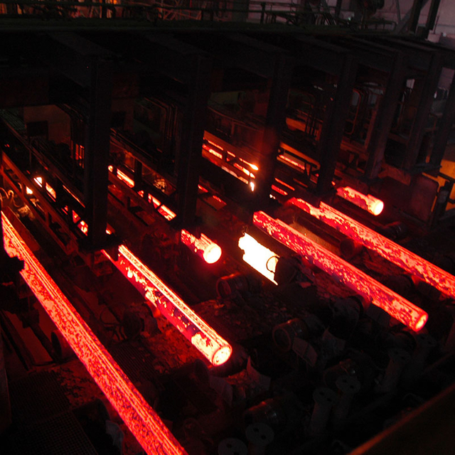
Capacity fluctuates significantly based on the steel grade being cast. The chemical composition of the melt dictates its solidification behavior, thermal conductivity, and crack sensitivity. Producing high-alloy or sensitive grades effectively reduces the hourly capacity of the machine compared to casting standard commercial-grade low-carbon steel.
Low Carbon Steels: Highly ductile and forgiving. Can be cast at maximum machine speeds with aggressive secondary cooling profiles.
Peritectic Steels (0.09% - 0.17% Carbon): Experience massive volume shrinkage during phase transformation in the mold. Highly prone to longitudinal surface cracking. Require slow casting speeds and very mild, uniform cooling.
High Carbon Steels: Prone to internal segregation. Require moderate speeds and hard cooling in the lower segments to prevent carbon migration to the center of the strand.
Micro-alloyed Steels: Contain niobium or vanadium. Susceptible to transverse cracking at the unbending point if the surface temperature falls into the ductility trough. Require precise thermal tracking.
Sequence casting maximizes the utilization factor within the capacity equation. It involves casting multiple ladles of steel consecutively without stopping the machine or inserting a new dummy bar. Flying tundish changes and optimized ladle turnaround times on the turret prevent machine stops. By maintaining a continuous flow of liquid steel, operations push actual production much closer to the theoretical maximum capacity.
A successful sequence can last for days or even weeks, depending on the wear life of the submerged entry nozzle (SEN) and the tundish refractory lining. Every time a sequence breaks, the machine must be stopped, the tail out processed, the dummy bar reinserted, and the mold repacked. This turnaround process can take over an hour, resulting in zero production and a massive hit to daily tonnage.
Breakouts devastate monthly capacity metrics. A breakout occurs when the liquid steel ruptures the solid shell, spilling molten metal into the containment segments. This forces an immediate shutdown, requiring extensive cleanup with oxygen lances and complete replacement of damaged rollers, hoses, and sensors. A single breakout can cause 12 to 24 hours of unplanned downtime.
To mitigate this risk, modern casters integrate breakout prediction systems. These systems rely on dense grids of thermocouples embedded in the copper mold plates. The system monitors the thermal profile for friction anomalies, detecting sticking or shell tearing. When the system detects a sticker breakout propagating down the mold, it automatically drops the casting speed to a crawl, allowing the shell to heal before ramping back up to operational speed. This technology maintains high average casting speeds safely and helps achieve yield improvements up to 98%.
Upgrading specific components offers a cost-effective path to boost capacity without pouring new foundations. Installing hydraulic mold oscillators replaces rigid mechanical cams, improving surface quality and allowing for higher speeds through dynamic stroke adjustments. Upgrading secondary cooling from straight water sprays to dynamic air-mist systems provides better temperature control and wider turndown ratios.
Extending the containment segment by adding another bow section increases the metallurgical length, directly raising the speed limit. Plant managers must weigh the downtime required for retrofitting against the projected tonnage increase. A segment extension might require a two-week outage, but the resulting 15% increase in casting speed pays off the capital expenditure within months.
Procurement teams sizing a greenfield installation must match upstream melt capacity with the target product mix. The decision framework requires evaluating current furnace output, ladle sizes, and future expansion plans. Designing for the future product mix ensures long-term viability.
If the market demands shift from standard rebar billets to near-net-shape thin slabs or specialized high-speed sheets, the caster must accommodate these geometries without becoming a bottleneck. Engineers must calculate the required metallurgical length based on the thickest section and the fastest desired speed, ensuring the building footprint can accommodate the necessary machine radius and runout tables.
Continuous caster capacity represents a dynamic equilibrium between mechanical design limits, metallurgical cooling realities, and operational sequence efficiency. Maximizing throughput requires aligning the caster with the melt shop, optimizing heat extraction in the mold, and maintaining long casting sequences. Equipping your continuous production lines with high-performance machinery and precise metallurgical engineering is essential for long-term productivity; partnering with established industrial manufacturers like WUXI LIWEI METALLURGY EQUIPMENT ensures that your continuous casting lines are built with durable heavy-duty mechanics, custom strand layouts, and reliable engineering support to achieve peak plant capacity. To improve your plant's overall performance, execute the following steps:
Conduct a comprehensive time-study audit of current melt shop pacing, focusing on EAF tap-to-tap times and ladle turret turnaround efficiency.
Prioritize equipment vendors offering robust thermodynamic modeling and dynamic air-mist cooling controls over those promising only high theoretical speeds.
Evaluate your future product mix to determine if near-net-shape casting, twin-belt systems, or multi-strand configurations best suit your downstream rolling strategy.
Assess the return on investment for retrofitting existing secondary cooling zones and hydraulic oscillators before committing capital to a full machine replacement.FAQ
A: Casting speeds vary widely based on the product cross-section. Thick slabs typically cast at 1 to 2 meters per minute. Standard billets cast between 2 and 5 meters per minute. Specialized twin-belt casters designed for thin strips can reach high-velocity speeds up to 14 meters per minute.
A: Multiple strands multiply the throughput of the machine. A 6-strand billet caster can process liquid steel six times faster than a single strand of the same size. This allows the caster to match high-volume furnace output without exceeding safe metallurgical withdrawal speeds on any individual line.
A: Metallurgical length is the physical distance from the mold meniscus to the point where the steel is completely solid. If casting speed is too high, the steel reaches the unbending rollers with a liquid core, causing severe internal cracks and potential breakouts.
A: You match them by aligning the caster's consumption rate in tons per hour with the EAF's tap-to-tap time and heat size. This synchronization prevents ladles from waiting too long on the turret, which causes temperature drops, or the caster running out of steel and breaking the sequence.
A: Breakouts occur when the solid steel shell exiting the mold is too thin or tears. This happens due to excessive casting speed, insufficient primary cooling in the copper mold, poor mold powder lubrication, or sticking friction between the solidifying shell and the mold plates.
A: Sequence casting involves pouring multiple ladles back-to-back without stopping the machine or reinserting the dummy bar. This eliminates the scrap generated at the start and end of a cast, maximizes machine uptime, and significantly improves overall yield and effective daily capacity.


