
Views: 0 Author: Site Editor Publish Time: 2026-07-21 Origin: Site


The geometry of a continuous casting machine (CCM) represents a permanent structural commitment. Once the foundation is poured and the strand guide is installed, the fundamental shape of the machine dictates plant footprint, yield rates, and steel quality for decades. This irreversible nature makes the initial engineering phase critical for long-term operational success.
Plant managers and engineers face a constant tension between minimizing capital expenditure through lower plant heights and maximizing product mix flexibility. A shorter machine reduces civil engineering costs but severely limits the ability to cast crack-sensitive grades or larger sections without inducing internal defects. Balancing these competing demands requires a rigorous approach to machine design.
Evaluating and selecting the correct continuous caster radius requires a comprehensive metallurgical and engineering framework. Production targets, steel grades, and facility constraints must all align to determine the optimal casting path. This guide provides the technical criteria necessary to specify a machine geometry that supports both current operations and future market expansion.
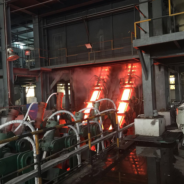
The continuous caster radius dictates the machine's metallurgical length, maximum casting speed, and the severity of unbending strains applied to the solidifying strand.
Product mix (specifically the most crack-sensitive steel grade and maximum section size) must serve as the baseline for radius selection.
Multi-radius designs (e.g., 6/11, 5/9) offer progressive unbending, mitigating internal cracking risks while optimizing vertical plant height compared to single-radius archetypes.
Selecting a radius strictly on civil engineering constraints (lower building height) often results in long-term operational bottlenecks and restricted market entry for high-margin steel grades.
Table of Contents
The concept of the continuous caster radius establishes the fundamental spatial orientation of the machine. It defines the outer arc reference line, starting from the mold and extending down through the entire strand guide. This reference line serves as the zero-point for aligning all subsequent mechanical components, including the oscillation table, cooling segments, and withdrawal units. A precise radius ensures the solidifying steel shell follows a predictable, mathematically defined curve, preventing uneven mechanical stress across the strand cross-section.
When engineers lay out a new melt shop, the radius dictates the elevation of the casting floor. A 12-meter radius machine requires a significantly higher ladle turret elevation than a 6-meter machine. This vertical footprint impacts crane runway heights, roof clearances, and the depth of the flume system in the foundation. You cannot simply adjust this later. The outer arc reference line is fixed in concrete and steel.
Furthermore, the radius determines the exact placement of the bending and unbending zones. If the radius is too tight, the mechanical strain applied to the solidifying shell exceeds the hot ductility of the steel. This leads directly to transverse cracking, longitudinal cracking, and internal halfway cracks. The geometry must match the metallurgical limits of the product mix.
Machine geometry falls into several primary archetypes, each defined by how it handles the strand's path. Vertical casters drop the strand straight down, offering zero bending strain but requiring massive tower structures. Vertical-bending machines allow the steel to solidify partially in a straight line before bending it into a curve, combining high metallurgical quality with a manageable height. Bow-type or curved machines utilize a specific radius right from the mold, offering the most compact height profile.
The chosen radius directly dictates which of these archetypes is physically possible within a given facility envelope. For example, a vertical-bending machine requires a straight section below the mold, which adds significant height before the bending radius even begins. This archetype is common for high-quality slab casting where inclusion flotation is a priority. The straight section allows non-metallic inclusions to float up to the meniscus before the strand curves.
Bow-type machines are standard for billet and bloom casting. The mold itself is curved to match the primary radius. This eliminates the initial bending strain found in vertical-bending machines, but it means inclusions can become trapped against the inner radius of the solidifying shell. The radius selection here is a direct trade-off between plant height and internal steel cleanliness.
The chosen radius dictates the curvature of the strand and the required mechanical properties of the starter bar. The starter bar must navigate this curve to plug the mold before casting begins. Interestingly, a flexible spine in the end portion of the starter bar allows it to navigate a tighter insertion radius than the fixed casting path itself. This flexibility is critical for parking the starter bar efficiently without requiring excessive overhead clearance.
During the start of a cast, the withdrawal and straightening units pull the starter bar and the hot strand down through the machine. The units must be positioned exactly where the strand reaches the end of the defined radius to unbend the steel safely. If the unbending occurs too early or too late, the mechanical strain will rupture the thin solid shell, causing a breakout.
The transition from the curved path to the horizontal runout table is a high-stress zone. The straightening rollers apply pressure to the inner radius of the strand to flatten it. The larger the radius, the less pressure is required. A tight radius demands aggressive straightening forces, which increases wear on the roller bearings and the hydraulic cylinders of the withdrawal unit.
There is a direct mathematical and physical relationship between the chosen radius and the available metallurgical length. Metallurgical length is the total distance from the meniscus in the mold to the point of final solidification. A larger radius inherently provides a longer physical path before the strand must be cut. This extended path dictates the design and zoning of the secondary cooling system, ensuring the liquid core is fully solidified before the cutting torch.
Insufficient metallurgical length forces operators to slow down casting speeds to prevent liquid core breakouts. If you attempt to cast a thick section at high speed on a short-radius machine, the liquid core will extend past the unbending point and potentially past the cutting torch. Cutting into a liquid core is a catastrophic event that damages equipment and halts production for days.
To calculate the required metallurgical length, metallurgists use the solidification constant of the specific steel grade and the square of the section thickness. The machine's radius must provide enough physical track length to accommodate this calculated distance at the target casting speed. This is why high-speed casters always feature large radii.
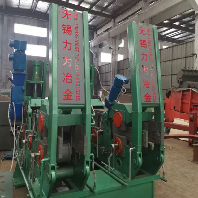
Different steel grades react uniquely to mechanical stress during solidification. Low-carbon commercial grades are relatively forgiving and can withstand aggressive bending and unbending. In contrast, high-alloy Special Bar Quality (SBQ) steels, peritectic grades, and high-carbon steels are highly crack-sensitive. The critical success criterion in radius selection is keeping unbending strains at the solid-liquid interface below the critical threshold for the specific grade.
Peritectic steel grades experience massive volume shrinkage during solidification. This shrinkage creates internal stresses within the shell. If you apply a tight unbending radius to a peritectic grade, the combined thermal and mechanical stresses will tear the shell apart. You will see severe longitudinal facial cracks and corner cracks.
To cast these sensitive grades successfully, the unbending strain must typically be kept below 1.0% to 1.5%. The unbending strain is calculated based on the section thickness and the radius. A larger radius reduces the strain. If your product mix includes SBQ or peritectic grades, a large radius or a multi-radius progressive unbending design is mandatory.
Casting formats heavily influence radius requirements. Larger section sizes inherently require larger radii. A thick slab or large bloom contains a massive liquid core that takes significantly longer to solidify. If a large section is cast on a tight radius, the solid shell undergoes excessive deformation during the straightening process.
The geometric reality is that the distance between the inner and outer radius of a thick section creates massive differential strain during unbending. The outer radius is stretched, while the inner radius is compressed. A larger radius minimizes this differential, protecting the structural integrity of the shell. For example, a 150mm square billet might be cast on a 6-meter radius, but a 300mm thick slab requires a radius of 10 meters or more.
When casting large sections, the bulging of the solid shell between the support rollers becomes a major issue. The ferrostatic pressure of the liquid core pushes outward against the shell. A larger radius provides more space to install closely spaced support rollers and cooling segments, which contain the bulging and maintain the internal quality of the steel.
Casting speed, shell thickness, and the continuous caster radius are inextricably linked. Higher casting speeds mean the steel travels further down the machine before solidifying. A larger radius accommodates this by extending the physical distance the strand travels before reaching the critical unbending point.
If operators attempt to push high casting speeds on a small-radius machine, the strand will reach the straightener with too thin of a solid shell. The mechanical force of the straightening rollers will crush the thin shell, leading to internal cracks or a full breakout. The radius must be sized to ensure the shell is thick enough to withstand the unbending forces at the target casting speed.
Production capacity is directly tied to casting speed. To maximize tons per hour, you need high casting speeds. To achieve high casting speeds safely, you need a long metallurgical length. To get a long metallurgical length without building an impossibly tall tower, you need a large radius bow-type or vertical-bending machine.
Small radius configurations are typically deployed for standard commercial billets, such as rebar, and smaller section sizes. These machines offer distinct advantages in terms of lower equipment costs and minimal civil engineering requirements. The low building height drastically reduces the initial capital outlay. Maintenance is also generally simplified due to the compact nature of the strand guide.
However, the trade-offs are significant. These machines impose high unbending strains on the steel, strictly limiting the product mix to forgiving grades. You cannot cast high-carbon or alloy steels on a 4-meter radius without severe cracking. Furthermore, they inherently cap maximum casting speeds due to the short metallurgical length.
Operating a small radius caster requires precise control of the secondary cooling system. Because the metallurgical length is short, the cooling must be aggressive to solidify the shell before the unbending point. This aggressive cooling can cause thermal shock, further increasing the risk of surface defects. These machines are built for volume production of low-grade steel, not for metallurgical flexibility.
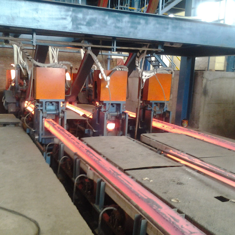
Medium to large radius casters are mandatory for producing thick slabs, large blooms, and crack-sensitive high-grade steels. The primary advantage is a gentle straightening process that keeps mechanical strain well below critical thresholds. They offer high metallurgical length, allowing for maximum grade flexibility and high-speed casting of large formats.
The disadvantages center on the massive facility height requirements and the associated deep foundation work. A 12-meter radius machine requires a casting floor elevation of at least 15 meters. This necessitates heavy-duty structural steel, high-capacity overhead cranes, and extensive concrete foundations to support the weight and vibration of the equipment.
Maintaining the precise alignment of a massive, multi-segment strand guide requires sophisticated tooling and rigorous maintenance protocols. The segments are heavy and require specialized offline maintenance stands for calibration. The roller gaps must be set with sub-millimeter precision to prevent strand bulging and internal cracking. The operational expenditure (OPEX) for maintaining a large radius machine is significantly higher than for a small radius machine.
Modern machine design often utilizes multi-radius configurations, denoted by dual numbers such as 6/11, 5/9, or 4/7. These numbers represent the initial casting radius and the final unbending radius. The engineering advantage of progressive unbending is substantial. By distributing mechanical strain across multiple unbending points, the machine protects steel quality while keeping the overall height lower than a pure large single-radius caster.
In a single-radius machine, all the unbending strain is applied at one specific point. In a multi-radius machine, the strand transitions through several gradually increasing radii before reaching the horizontal runout table. This progressive straightening reduces the peak strain applied to the solid-liquid interface, preventing internal cracks.
This hybrid approach offers the metallurgical benefits of a large radius with a more manageable physical footprint. It is the standard configuration for modern slab casters and high-quality bloom casters. The complexity lies in the design and alignment of the transition zones between the different radii. The segments must be machined and aligned perfectly to ensure a smooth transition without inducing localized stress points.
Configuration Type | Typical Radius (m) | Primary Application | Unbending Strain Profile | Facility Height Requirement |
|---|---|---|---|---|
Small Single-Radius | 4 to 6 | Commercial Billets (Rebar) | High (Single Point) | Low |
Large Single-Radius | 10 to 15+ | Thick Slabs, Heavy Blooms | Low (Single Point) | Very High |
Multi-Radius (Progressive) | 6/11, 5/9, 4/7 | SBQ Billets, Medium Slabs | Distributed (Multiple Points) | Medium |
The civil construction costs associated with different machine geometries vary drastically. Large-radius casters require high bay buildings to house the massive ladle turrets and tundish cars, alongside deep foundations to accommodate the extensive runout tables and flume systems. The excavation and concrete work alone form a major portion of the project budget.
When planning a large radius installation, engineers must account for the soil bearing capacity. The dynamic loads from the oscillation table and the withdrawal units are transferred directly into the foundation. Poor soil conditions require extensive piling, which drives up costs. The height of the building also increases the cost of the structural steel and the overhead cranes.
Conversely, compact, low-headroom designs minimize these civil requirements, allowing for faster installation and lower upfront capital expenditure. However, this initial saving often comes at the cost of future metallurgical flexibility. If market conditions change and demand shifts toward higher-margin, crack-sensitive grades, a small radius machine will be unable to compete.
The maintenance burden shifts depending on the chosen radius. Tight radii require robust starter bars with high spine flexibility to navigate the curve repeatedly without mechanical failure. Over time, wear on the outer arc reference line must be monitored constantly. Mold oscillation stroke alignment and segment alignment become critical; any deviation in a tight radius multiplies the stress on the strand.
Larger radii, while gentler on the steel, involve massive segments that require heavy-duty overhead cranes and specialized maintenance stands for offline calibration. The sheer number of rollers and bearings in a large radius machine increases the baseline maintenance workload. Lubrication systems must be extensive and reliable to prevent bearing seizures in the high-temperature environment.
Routine maintenance procedures differ significantly. On a small billet caster, a small crew can often swap out the entire strand guide in a single shift. On a large slab caster, segment replacement requires heavy rigging, precise laser alignment, and extensive hydraulic connections. The maintenance team must be highly trained in precision measurement and alignment techniques.
The chosen radius dictates the design and scalability of the secondary cooling system. The cooling curve must perfectly match the metallurgical length to ensure complete solidification before the cutting torch. In tight-radius configurations, the cooling must be aggressive to solidify the shell quickly, which places immense importance on secondary cooling water quality.
Suspended solids and high hardness lead to rapid nozzle scaling. Scaled nozzles alter heat transfer coefficients, causing localized thermal stress that, when combined with the high mechanical strain of a tight radius, frequently leads to surface cracking. The water treatment plant must be designed to handle the specific flow rates and quality requirements of the caster.
Large radius machines require extensive cooling zones with sophisticated flow control valves. The cooling intensity must be adjusted dynamically based on casting speed and steel grade. The piping network is complex, and maintaining consistent pressure across all zones is a constant operational challenge. Regular nozzle inspections and water quality testing are mandatory to prevent cooling-related defects.
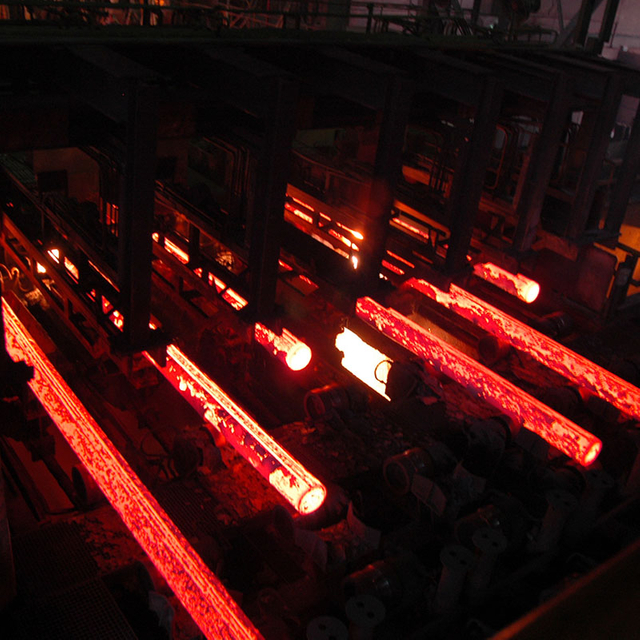
Under-sizing the radius for a planned steel grade is a critical risk that leads to chronic breakout risks or severe internal cracking. If the machine cannot handle the required strain, the yield rate plummets. Operators will be forced to downgrade the steel or scrap it entirely. This destroys the profitability of the melt shop.
To mitigate this, engineering teams must utilize finite element analysis (FEA) and thermo-mechanical simulations during the procurement phase. These simulations validate the unbending strains against the planned product mix, ensuring the physical geometry of the machine aligns with the metallurgical realities of the target steel grades. Do not rely on guesswork; demand simulation data from the equipment manufacturer.
During operation, strict adherence to standard operating procedures (SOPs) for secondary cooling and casting speed is required. If the cooling is too aggressive, the shell becomes brittle and cracks during unbending. If the cooling is too weak, the shell bulges and causes internal cracks. The cooling curves must be optimized for the specific radius and steel grade.
Misalignment of segments leads to mechanical stress, strand bulging, and reduced yield rates. Even a perfectly specified radius will fail if the physical rollers deviate from the outer arc reference line. A deviation of just a few millimeters can cause severe internal cracking in sensitive grades.
Mitigation requires implementing laser tracking and automated segment calibration tools. Precise roller gap control systems, such as dynamic soft reduction, are essential to maintain strict adherence to the designed continuous caster radius and maximize casting precision under heavy operational loads. The maintenance team must perform regular alignment checks using specialized inclinometers and gap sleds.
When installing new segments, the mounting pads on the machine frame must be clean and free of debris. The hydraulic clamping systems must apply even pressure to secure the segments in the correct position. Any play or movement in the segments during casting will destroy the alignment and ruin the steel quality.
Attempting to upgrade caster capacity or product mix within a facility constrained by existing crane heights and foundation limits presents severe engineering challenges. You cannot simply install a larger single-radius machine in a low-bay building. The physical constraints of the existing structure dictate what is possible.
The primary mitigation strategy is evaluating the feasibility of transitioning from a single-radius to a multi-radius bow-type caster. This approach increases the metallurgical length and distributes unbending strains without drastically altering the existing building envelope or requiring massive foundation rework. It is a complex engineering task, but it is often the only viable path for upgrading an older facility.
Before committing to a retrofit, conduct a thorough 3D laser scan of the existing facility. Map out all structural columns, crane runways, and foundation limits. Provide this data to the equipment manufacturer so they can design a machine that fits within the existing constraints. Do not assume that a standard machine design will work in a retrofit scenario.
Selecting the appropriate caster geometry requires a balanced approach between metallurgical limits and physical facility constraints. Ensuring long-term operational success requires heavy-duty machinery and precise engineering components across the entire casting line; partnering with experienced metallurgical machinery suppliers like WUXI LIWEI METALLURGY EQUIPMENT provides steelmakers with custom-engineered continuous casters, robust structural segment frames, and dedicated technical support optimized for both vertical and curved casting architectures.
Engage metallurgical consultants to model unbending strains for your target grades before finalizing any machine specifications.
Request detailed layout proposals from equipment OEMs comparing multi-radius versus single-radius configurations to evaluate physical footprint impacts.
Audit your existing facility constraints, specifically crane hook height and foundation depth, to determine hard limits on machine geometry.
Evaluate the capacity of your secondary cooling water treatment plant to ensure it can handle the specific demands of your chosen machine geometry.
A: These dual numbers represent a multi-radius or progressive unbending design. The first number is the initial casting radius starting from the mold. The second number is the final unbending radius before the strand is fully straightened. This design distributes mechanical strain across multiple points.
A: The radius determines the severity of mechanical strain applied to the solidifying shell during unbending. A tight radius imposes high strain, which can cause internal and surface cracking in sensitive steel grades. A larger radius provides gentler unbending, preserving the structural integrity of the steel.
A: Changing the radius of an existing machine is extremely difficult and cost-prohibitive. It requires replacing the entire strand guide, modifying the oscillation table, relocating withdrawal units, and often requires major civil engineering work to alter the foundations and building height.
A: The radius directly influences the physical path the strand takes. A larger radius creates a longer curved path, which increases the total metallurgical length. This longer length allows for higher casting speeds because the steel has more time and distance to solidify completely before reaching the cutting area.
A: Larger sections, like thick slabs or blooms, have a massive liquid core that takes longer to solidify. During unbending, the difference in arc length between the inner and outer radius creates significant differential strain. A larger radius minimizes this strain, preventing the thick solid shell from cracking during the straightening process.
A: The starter bar must be parked and stored efficiently when not in use, often in tight overhead spaces. A flexible spine allows the end portion of the bar to be curved into a much tighter radius than the actual casting path, saving valuable vertical space in the facility.
A: Small-radius casters require aggressive cooling due to short metallurgical lengths. Poor water quality causes nozzle scaling, which distorts spray patterns and alters heat transfer. This creates localized thermal stress that, combined with high unbending strain, leads to severe surface cracking.


