
Views: 0 Author: Site Editor Publish Time: 2026-08-17 Origin: Site


A continuous casting breakout halts production, damages equipment, and creates severe safety hazards on the cast floor. When molten steel breaches the fragile solidified shell within or immediately below the mold, the resulting spill causes days of unplanned downtime. The financial impact hits hard through lost yield, extensive machine repairs, and the heavy labor required to lance solidified steel off the casting segments. The core problem is the failure mechanism itself. Molten steel penetrates or ruptures the shell rapidly. Detecting these micro-failures before they propagate into a full-scale breach is difficult. Liquid steel pushing against a thin, newly formed shell creates massive ferrostatic pressure. If the shell weakens from poor lubrication, uneven cooling, or mechanical stress, it tears. Effective continuous casting breakout prevention requires a multi-layered approach. You must integrate strict process control, rigorous mechanical maintenance, and advanced Breakout Prediction Systems (BOPS).
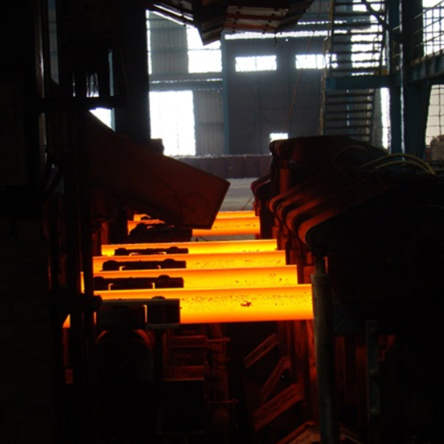
Speed Control is the Primary Mitigation: Immediate reduction of casting speed is the most reliable countermeasure to recover a sticker and prevent a full breakout by increasing residence time in the mold.
Maintenance Equals Prevention: Mechanical integrity—specifically mold alignment, taper optimization, and cooling system efficiency—is the foundational layer of any breakout prevention strategy.
Advanced Prediction Systems (BOPS) are Mandatory: Modern operations require intelligent, logic-based or AI-driven BOPS utilizing dense thermocouple or fiber-optic networks to detect thermal anomalies before shell rupture.
Data-Driven Root Cause Analysis: Leading facilities leverage machine learning not just for real-time prediction, but to diagnose the root causes of near-misses in minutes, driving continuous process improvement.
False Positives vs. Throughput Trade-offs: Evaluating BOPS technology requires balancing the sensitivity of sticker alarms against the production losses incurred by unnecessary speed reductions.
Table of Contents
Sticker breakouts represent the most frequent failure mode in continuous casting operations. The failure sequence initiates at the meniscus, the exact line where liquid steel meets the water-cooled copper mold. If the mold flux fails to provide adequate lubrication, or if localized heat transfer drops unexpectedly, the solidifying steel shell bonds directly to the copper mold wall. The drive rolls below the mold continuously pull the strand downward. The bonded section remains stuck to the copper, while the rest of the shell moves. This opposing mechanical force rips the thin shell apart.
As the strand withdraws, fresh liquid steel rushes into the open tear. This new steel briefly solidifies against the copper before the downward pulling force tears it open again. This repetitive tearing and freezing cycle generates a distinct "V-shaped" thermal pattern that travels down the mold face. If operators or automated systems fail to reduce the casting speed immediately, the torn section will not have time to heal. The liquid core will breach the shell the exact second it exits the bottom of the mold.
Crack breakouts happen when the solidified shell develops deep longitudinal or transverse fissures that penetrate straight through to the liquid core. Longitudinal cracks usually originate from uneven cooling inside the mold or improper mold flux chemistry. Casting peritectic steel grades (typically between 0.09% and 0.17% carbon) presents a massive challenge here. These grades undergo a massive volume contraction during the delta-to-gamma phase transformation. This rapid shrinkage pulls the shell away from the mold unevenly, causing hot spots and deep surface cracks. If the casting speed remains too high, the shell stays too thin to handle the internal ferrostatic pressure, and these cracks burst open.
Hanger breakouts are mechanical failures. They occur when a physical obstruction stops the downward movement of the strand. A deep gouge in the copper mold plate, severe mold wear, or a misaligned segment zero immediately below the mold can catch the shell. The drive rolls keep pulling, generating extreme tensile stress that eventually rips the strand in half. Maintaining the surface quality of the copper plates and the alignment of the upper segments prevents hanger incidents.
Bleeder breakouts are sudden, highly localized ruptures that usually occur just below the mold exit. Unlike a sticker, a bleeder does not propagate down the mold; it blows out instantly. Deep oscillation marks act as primary stress concentrators. These marks form at the meniscus during the mold's upward stroke. If the oscillation parameters are incorrect, these marks become too deep, leaving the shell dangerously thin at that specific horizontal line.
Slag entrapment also triggers bleeders. If turbulent flow in the mold pulls liquid mold slag deep into the solidifying shell, the slag creates an insulating pocket. The steel surrounding this slag pocket cannot transfer heat to the copper mold. The result is a localized hot spot where the shell remains paper-thin. Once this weak point clears the supportive copper mold, the internal pressure of the liquid steel blows out the thin shell.
A functional prevention program relies on hard metrics. The absolute baseline is zero catastrophic liquid steel breaches. However, you cannot achieve this simply by running the caster at a crawl. Slow casting destroys plant profitability and disrupts the pacing of the entire steelmaking facility. Therefore, a secondary metric is optimizing average casting speeds while maintaining strict safety margins.
The third metric involves minimizing false sticker alarms. Every time a prediction system triggers a false alarm, the automation drastically reduces casting speed to let the non-existent tear heal. This transient state disrupts mold level stability, degrades the surface quality of the steel, and cuts daily throughput. Balancing high detection sensitivity with a low false-positive rate separates average plants from world-class operations.
Common Continuous Casting Breakout Types and Primary Causes
Breakout Type | Primary Mechanism | Root Causes | Detection Method |
|---|---|---|---|
Sticker (Bond) | Shell bonds to copper mold, tearing as strand withdraws. | Lubrication failure, flux crystallization, meniscus level fluctuation. | Thermal inversion tracking (BOPS). |
Longitudinal Crack | Uneven shrinkage causes vertical fissures. | Uneven cooling, peritectic steel grades, improper mold taper. | Mold thermal mapping, visual inspection. |
Hanger | Mechanical obstruction stops strand movement. | Mold plate damage, severe misalignment, excessive wear. | Friction monitoring, mold level drops. |
Bleeder | Localized thin spot ruptures below mold. | Deep oscillation marks, entrapped mold slag. | Sub-mold thermal cameras, secondary cooling monitoring. |
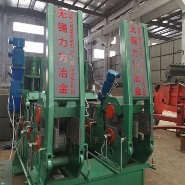
Casting speed dictates shell thickness. Residence time—the exact number of seconds the steel spends inside the water-cooled mold—controls heat extraction. Slower casting speeds increase residence time, building a thicker, stronger shell capable of holding back the liquid core. Pushing the machine to higher speeds (e.g., moving from 1.0 m/min to 1.6 m/min on a slab caster) thins the shell and removes your margin for error.
Transient states demand strict standard operating procedures. During the initial pour and dummy bar disconnect, the process lacks thermal stability. Operators must hold a slow, controlled speed—typically around 0.5 m/min—until the mold level stabilizes and the shell makes uniform contact with the copper plates. The machine can only ramp up to steady-state production speeds after clearing this vulnerable phase.
Dynamic speed reduction is the primary defense mechanism against a sticker. When a thermal alarm triggers, the system executes a specific recovery sequence:
The BOPS detects a thermal inversion and triggers a Level 1 automation alarm.
The PLC automatically drops the casting speed to a creep (typically 0.1 to 0.2 m/min).
The operator monitors the thermal map as the V-shaped defect travels downward.
The defect clears the bottom row of mold sensors, indicating the torn shell has healed.
The automation slowly ramps the casting speed back to steady-state production levels.
Mold powder is a synthetic slag that controls the cast. Operators add it to the top of the liquid steel, where it melts and flows down into the gap between the solidifying shell and the copper mold. This liquid flux layer provides hydrodynamic lubrication to prevent sticking and regulates the heat transfer rate from the steel to the cooling water.
Flux chemistry directly impacts breakout risk. If the viscosity is too high, the flux fails to flow evenly into the gap. This creates localized dry spots where the steel bonds to the copper. Incorrect melting rates cause the powder to bridge or form solid rims, which disrupt the meniscus. Furthermore, as the flux absorbs alumina from the liquid steel, its chemical composition shifts. This alumina pickup increases viscosity and alters the crystallization temperature, suddenly degrading lubrication and triggering a sticker breakout.
The mold oscillates vertically to prevent the steel from sticking to the copper walls. The critical parameter here is negative strip time. This is the fraction of a second during the downward stroke when the mold travels faster than the casting speed. Negative strip time compresses the fragile shell, heals micro-tears, and physically strips the steel away from the mold wall. Precise hydraulic oscillation control, allowing on-the-fly adjustments to stroke length and frequency, is mandatory for breakout prevention.
Below the mold, the strand enters the secondary cooling zone. Banks of water sprays continue the solidification process. Spray distribution must be perfectly uniform. If nozzles clog or misalign, one side of the shell cools faster than the other. This induces massive thermal stresses, causing internal cracks to propagate to the surface. Proper secondary cooling management ensures symmetrical shell growth, preventing sub-mold ruptures.
Copper mold plates endure extreme thermal cycling and mechanical friction. The copper wears down over time, changing the internal dimensions of the mold. Because steel shrinks as it cools, the mold plates must be precisely tapered to match this specific shrinkage profile. If the mold loses its proper taper due to wear or thermal distortion, the copper loses contact with the shrinking steel shell.
When the shell pulls away from the copper, an air gap forms. Air acts as an insulator. Heat transfer drops to near zero in that specific area, and shell growth stops entirely. The resulting thin spot is highly susceptible to tearing. Maintenance teams must enforce strict inspection intervals for mold plating thickness, dimensional verification, and taper recalibration. Using advanced inclinometers ensures the taper remains optimized for the specific steel grade in the schedule.
The containment rolls immediately below the mold support the fragile strand. Misalignment in these rolls induces severe mechanical stress. If a roll is pushed too far inward, it crushes the shell. If a roll is pulled too far outward, the shell bulges under internal ferrostatic pressure. This bulging leads to hinge cracks and eventual rupture.
Maintaining the structural integrity of the casting segments requires constant vigilance. Bearings fail, roll surfaces wear unevenly, and segment frames warp under continuous heat exposure. Routine maintenance must include dropping roll gap sleds through the machine during down days to measure the exact gap and roll rotation. A perfectly aligned machine distributes support evenly, allowing the shell to thicken without bending or bulging.
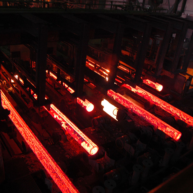
Cooling system maintenance is breakout prevention. The primary cooling system pushes high-velocity water through channels inside the copper mold. If plant water chemistry degrades, calcium carbonate and other minerals precipitate out, forming scale on the inside of the copper water jackets. A scale layer just one millimeter thick drastically reduces heat transfer, causing localized hot spots on the mold face and uneven shell growth.
Secondary cooling relies on hundreds of individual air-mist or hydraulic spray nozzles. In the harsh environment of a caster, these nozzles frequently clog with debris, scale, or degraded casting powder. A clogged nozzle creates a dry band on the strand. The steel in this band reheats from the liquid core, loses its structural strength, and bulges. Maintenance must execute regular water chemistry audits, acid flush mold water channels, and systematically clean secondary cooling nozzles.
Maintenance Inspection Intervals for Caster Components
Component | Inspection Task | Frequency | Impact on Breakout Prevention |
|---|---|---|---|
Copper Mold Plates | Measure wear profile and plating thickness. | After every casting sequence. | Prevents air gaps and localized thin spots in the shell. |
Mold Taper | Verify narrow face taper with inclinometer. | Before every cast start. | Ensures copper maintains contact with shrinking steel. |
Segment Zero Rolls | Check roll gap and rotation with measurement sled. | Weekly down day. | Prevents mechanical crushing or bulging of the fragile shell. |
Secondary Cooling Nozzles | Visual spray pattern check and flow test. | Weekly down day. | Prevents uneven cooling and longitudinal crack propagation. |
Mold Water Channels | Acid flush to remove mineral scale buildup. | Quarterly. | Maintains maximum heat transfer efficiency through the copper. |
Traditional Breakout Prediction Systems rely on dense arrays of Type-K thermocouples embedded in the copper mold plates. These sensors provide point-based thermal mapping, tracking temperature changes at specific locations. While robust and proven, thermocouples have inherent blind spots between the sensor points. If a localized tear occurs exactly between two thermocouples, the system might not detect the thermal spike until the tear propagates further down the mold.
High-resolution fiber-optic sensor networks represent the next generation of thermal monitoring. Fiber Bragg Grating (FBG) sensors measure temperatures continuously along the entire length of the fiber. This provides a high-definition thermal map of the mold face, eliminating blind spots. When evaluating these systems, engineers must compare the rapid response time and spatial resolution of fiber optics against their maintenance requirements. Fiber cables are delicate and harder to replace in a harsh steel plant environment than traditional thermocouples.
Early prediction systems relied on simple threshold-based alarms. If a thermocouple exceeded a specific temperature, the alarm triggered. This approach generated massive numbers of false positives due to normal mold level fluctuations. Modern systems utilize intelligent logic-based algorithms that track thermal inversion patterns. They monitor the temperature difference between upper and lower sensor rows, specifically looking for the V-shaped thermal signature of a propagating tear.
The industry now utilizes AI-driven detection. Machine learning algorithms analyze years of historical breakout data, learning to distinguish between a genuine sticker tear and a harmless thermal fluctuation caused by slag rim detachment. By improving pattern recognition, AI systems drastically reduce false positive rates. Operators learn to trust the system, knowing that an alarm represents a genuine threat rather than a software glitch.
Modern prediction platforms act as comprehensive diagnostic tools. Leading AI platforms utilize high-frequency BOPS thermal data synchronized with Level 2 process variables—such as casting speed, mold level, oscillation friction, and slide gate position—to perform rapid root cause analysis. When a near-miss or a breakout occurs, the system diagnoses the exact sequence of events in minutes.
Instead of engineers spending days pulling data logs and debating the cause, the software highlights the anomaly. It might show that a sudden drop in mold water flow preceded the thermal inversion, or that abnormal oscillation friction caused the initial meniscus tear. This rapid RCA capability drives continuous process improvement, allowing metallurgists to adjust standard operating procedures immediately to prevent a recurrence.
A prediction system only works if it communicates seamlessly with the machine's control architecture. Evaluating BOPS requires assessing its scalability and ease of integration with existing Level 1 (PLC) and Level 2 (process automation) systems. The thermal data must flow into the PLC with millisecond latency to trigger automated speed reductions.
The solution must adapt across different caster designs. Slab casters require massive sensor arrays across wide copper faces, while bloom and billet casters deal with tight radii and different cooling dynamics. A robust BOPS platform offers standardized integration protocols, allowing a steel producer to deploy the same analytical software across their entire fleet of casting machines.
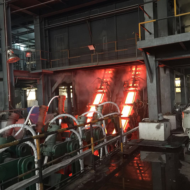
Tuning the algorithm's sensitivity is the hardest implementation challenge. If you make the BOPS highly sensitive, it catches every micro-tear and prevents all sticker breakouts. However, this hyper-sensitivity triggers numerous false alarms. Every false alarm forces an unnecessary reduction in casting speed, which disrupts the thermal stability of the strand, degrades surface quality, and costs the plant significant production tonnage.
If you desensitize the algorithm to maximize throughput and eliminate false alarms, you risk missing a genuine sticker tear. A single missed breakout costs millions in equipment damage and lost operating days. Technical teams must continuously analyze their false-positive ratios and adjust the logic parameters to find the optimal balance between asset protection and production efficiency.
Thermal sensors operate millimeters away from liquid steel. The extreme operating environment—characterized by intense heat, aggressive cooling water, and constant mechanical vibration—causes sensor degradation over time. Thermocouples experience calibration drift, where their temperature readings become inaccurate. If the BOPS relies on drifting data, its pattern recognition algorithms fail.
Mitigating this risk requires automated sensor health monitoring. Modern systems detect when a specific thermocouple begins to drift or fail, automatically excluding it from the logic calculation and alerting maintenance. Plants must enforce strict recalibration schedules and replace degraded sensors during routine mold rebuilds to ensure the prediction system always operates with clean, accurate data.
The human element remains the weakest link in process safety. If a prediction system generates too many false positives, operators develop alarm fatigue. They begin to distrust the system, hesitate to reduce speed, or manually override the alarms to maintain production targets. This behavior completely negates the value of the BOPS investment.
The most effective mitigation tactic is implementing automated closed-loop responses. In a closed-loop setup, the BOPS communicates directly with the drive rolls. When a sticker pattern is confirmed, the system automatically reduces the casting speed to the required recovery level without waiting for operator intervention. This removes human hesitation from the critical path, ensuring the machine protects itself instantly while reducing the cognitive load on the operators.
Audit current mold maintenance procedures immediately, focusing on taper measurement accuracy and copper wear limits.
Calculate the annual tonnage lost to unnecessary speed reductions to evaluate your existing BOPS false-positive rates.
Upgrade legacy threshold-based alarms to intelligent logic-based or AI-driven pattern recognition systems to improve detection accuracy.
Implement closed-loop automation between the BOPS and the PLC to remove operator hesitation during critical thermal alarm events.
Establish a daily routine for metallurgists to review BOPS thermal data and identify near-miss root causes before they escalate.
For steel plants seeking to strengthen breakout prevention, working with an experienced metallurgical equipment partner can help integrate caster design, process control, maintenance practices, and automation into a more reliable production system. WUXI LIWEI METALLURGY EQUIPMENT CO., LTD has served the metallurgical industry since 1998, providing engineering design, equipment manufacturing, installation, commissioning, and complete solutions covering steel melting, continuous casting machines, and rolling mills for customers in international markets.
A: A sticker breakout occurs when lubrication fails at the meniscus. If mold flux does not flow properly, the solidifying steel shell bonds directly to the copper mold. As the drive rolls pull the strand downward, this bonded section tears open, allowing liquid steel to breach the shell.
A: Casting speed controls the residence time of the steel inside the water-cooled mold. Higher speeds reduce residence time, resulting in a thinner, weaker solidified shell. Reducing the casting speed increases residence time, allowing the shell to thicken and withstand internal ferrostatic pressure.
A: Peritectic steel grades undergo a massive volume contraction during the delta-to-gamma phase transformation as they cool. This rapid, uneven shrinkage pulls the shell away from the mold walls, causing localized hot spots and severe longitudinal cracks that can rupture under pressure.
A: Negative strip time is the specific fraction of a second during the mold's downward oscillation stroke when the mold travels faster than the casting speed. This action compresses the fragile shell, heals micro-tears, and physically strips the steel away from the copper wall.
A: Thermocouples measure temperature at specific, isolated points, leaving blind spots between sensors. Fiber-optic sensors measure temperature continuously along the entire length of the fiber cable, providing a high-definition thermal map of the mold face and eliminating blind spots for earlier tear detection.
A: A closed-loop response means the Breakout Prediction System is directly integrated with the machine's drive roll automation. When the system detects a breakout pattern, it automatically reduces the casting speed to heal the shell, eliminating the delay associated with waiting for a human operator to react.


