Views: 0 Author: Site Editor Publish Time: 2026-07-21 Origin: Site


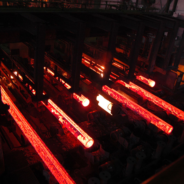
Acquiring a continuous casting machine (CCM)—often referred to as a strand casting machine—represents a high-stakes capital expenditure for any steel plant. Miscalculations during the specification phase directly impact plant yield, metallurgical quality, and operational bottlenecks for decades. The core operational friction in most facilities stems from mismatched capacities. Specifically, plants fail to synchronize the melt shop's output with the caster's throughput and the rolling mill's feed requirements, leading to stranded steel or idle mills. To resolve these bottlenecks, engineering teams need a structured evaluation framework for billet caster selection. This guide breaks down the exact machine specifications, metallurgical control features, and downstream integration requirements necessary to ensure long-term operational stability and risk mitigation.
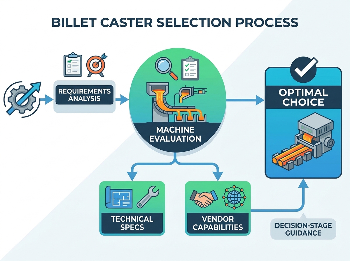
Capacity Synchronization is Non-Negotiable: Successful selection requires exact matching between furnace heat sizes, ladle transport times, and strand counts to prevent temperature losses and production delays.
Metallurgical Quality Dictates Machine Design: The choice of machine radius, mold oscillation, and cooling zones must be driven by the target steel grades (commercial vs. special steel) and billet formats (100mm–200mm) being produced.
Speed vs. Stability Trade-offs: While modern casters can achieve speeds up to 6 m/minute, high-speed casting requires advanced electromagnetic stirring (EMS), precise mold level control, and dynamic secondary cooling to prevent internal defects and breakouts.
Table of Contents
You must establish a strict mathematical relationship between furnace tapping weight, heat cycle time, and required caster throughput. A mismatch here forces either the furnace to wait or the continuous casting machine to halt. Applying the matching principles of continuous casting machines ensures continuous sequence casting. This prevents ladle cooling issues and eliminates artificial bottlenecks. Calculate your exact ladle transport times and match them against the casting duration per heat. The goal is a continuous handover where the tundish never runs dry.
For example, a 50-ton Electric Arc Furnace (EAF) with a 45-minute tap-to-tap time requires a caster capable of processing 50 tons within that exact 45-minute window, factoring in ladle transfer and argon stirring times. If the caster throughput is only 40 tons in 45 minutes, the melt shop must slow down, destroying plant efficiency. Conversely, if the caster processes 60 tons in 45 minutes, it will drain the tundish before the next heat arrives, breaking the sequence. Engineers must calculate the mass flow rate per strand based on the billet cross-section and casting speed, then multiply by the number of strands to find the total machine throughput.
Machine design requirements contrast sharply between commodity steels and Special Bar Quality (SBQ) alloys. Low-carbon construction rebar allows for aggressive cooling and simpler machine profiles. SBQ demands stringent internal quality controls. Your target product mix directly impacts the choice of machine radius. It also dictates the necessity of electromagnetic stirring (EMS) and specialized secondary cooling configurations.
When casting commercial grades like standard 500MPa rebar, the primary objective is maximum tonnage. Surface cracks are less of a concern due to the high reduction ratios in the rolling mill, allowing for aggressive water spray cooling. However, casting crack-sensitive grades like 42CrMo4 or high-carbon wire rod requires a completely different approach. These grades suffer from internal segregation and surface cracking if subjected to high mechanical strain or uneven cooling. Therefore, SBQ casters require larger machine radii to minimize unbending strains and sophisticated air-mist cooling to maintain a uniform surface temperature above the ductility trough.
Parameter | Commercial Grades (e.g., Rebar) | Special Bar Quality (SBQ) |
|---|---|---|
Machine Radius | Smaller radius acceptable (4-6m) | Larger radius required (9-12m) |
Cooling Strategy | Aggressive water spray | Dynamic air-mist cooling |
Electromagnetic Stirring | Optional, often omitted | Mandatory (M-EMS and S-EMS) |
Unbending Strains | High tolerance | Low tolerance (crack-sensitive) |
Mold Oscillation | Standard mechanical | Hydraulic with dynamic stroke |
Matching billet cross-sections to the roughing mill's reduction ratio dictates downstream success. Small billets feature cross sections less than or equal to 150x150mm. Larger commercial formats exceed these dimensions. You must evaluate the technical requirements for hot charging or direct charging. Caster exit temperatures heavily influence energy consumption in the reheating furnace. Higher exit temperatures reduce the thermal load on downstream heating equipment.
If your roughing mill is designed to accept 130x130mm billets, selecting a caster optimized for 160x160mm billets will cause severe pass schedule issues and overload the mill stands. Furthermore, modern plants utilize hot direct rolling (HDR) to save energy. To achieve this, the billet must exit the caster and enter the reheating furnace at temperatures exceeding 800°C. This requires insulated roller tables and rapid discharge mechanisms. The caster's secondary cooling zones must be tuned to ensure the billet retains sufficient core heat without compromising complete solidification before the cutting torch.
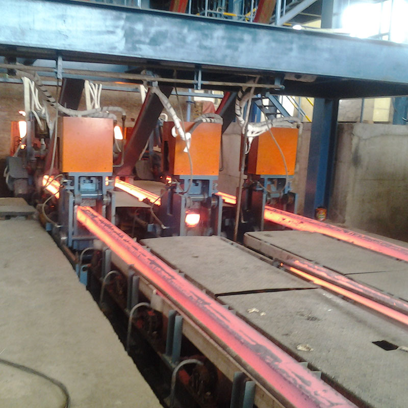
Calculating the optimal number of strands requires analyzing annual tonnage targets and average casting speeds. Configurations range from single-strand setups for boutique alloy plants up to 8-strand machines for high-volume commercial steel producers. You must address the physical footprint, workshop height, and plant layout constraints. Expanding strand counts laterally requires sufficient space for the cooling bed and discharge roller tables.
To determine the correct strand count, follow these calculation steps:
Determine the target annual production tonnage (e.g., 600,000 tons).
Calculate the available annual operating hours, factoring in planned maintenance and turnaround times (typically 7,000 to 7,500 hours).
Divide the annual tonnage by the operating hours to find the required hourly throughput.
Calculate the mass flow rate of a single strand based on the target billet size, steel density, and average casting speed.
Divide the required hourly throughput by the single-strand mass flow rate to determine the minimum number of strands.
Add one additional strand if high operational flexibility or frequent size changes are anticipated.
Curved casting machines dominate the market due to their lower height requirements. Vertical-bending designs offer superior inclusion flotation. The bending radius directly impacts the unbending strains exerted on the solidifying shell. Crack-sensitive special steel grades require larger radii to minimize internal stress during the unbending phase. Proper profile selection prevents transverse cracking in alloyed billets.
A standard curved caster with a 6-meter radius is sufficient for low-carbon steels. The molten steel enters the curved mold and follows a continuous arc until it reaches the horizontal plane. However, for high-quality automotive components or bearing steels, non-metallic inclusions must float to the surface meniscus in the mold. A vertical-bending caster provides a straight vertical section (usually 2 to 3 meters) immediately below the mold. This straight section allows inclusions to rise unhindered by the inner radius curve. After the vertical section, the strand is progressively bent into a curve and then unbent to horizontal. This multi-point unbending distributes the mechanical strain, keeping it below the critical 1.5% threshold for crack-sensitive grades.
The tundish acts as a buffer and a metallurgical reactor between the ladle and the mold. Tundish capacity requirements must align with heat size to facilitate stable sequence casting. A larger volume promotes inclusion flotation and temperature homogenization. You must also compare flow control systems. Stopper rod mechanisms offer precise molten steel flow regulation for SBQ. Slide gate systems provide robust reliability for commercial grades.
A well-designed tundish provides a minimum residence time of 8 to 10 minutes for the molten steel. This duration allows alumina and silica inclusions to float into the covering slag. Internal furniture, such as weirs, dams, and impact pads, directs the fluid flow to prevent dead zones and short-circuiting. When evaluating flow control, stopper rods are preferred for closed-stream casting with submerged entry nozzles (SEN), which is mandatory for aluminum-killed steels to prevent reoxidation. Metering nozzles with slide gates are standard for open-stream casting of silicon-killed commercial billets, offering lower maintenance complexity and faster turnaround times between sequences.
Assess the machine's capability to switch between square and round formats. Square billets feed structural shape mills, while round billets serve seamless tube and forging applications. Detail the tooling and cartridge-change systems required for size transitions. Quick-change mold assemblies reduce downtime when shifting mold sizes within the standard commercial range of 100 mm up to 200 mm.
Modern casters utilize modular mold cartridges. Instead of dismantling the entire oscillator and water jacket, maintenance crews lift the entire cartridge out as a single unit and drop in the new size. This reduces size changeover times from 8 hours to under 2 hours. When evaluating a machine, verify the alignment tolerances of the quick-change system. Misalignment between the mold and the first cooling zone (Zone 1) causes uneven shell growth, leading to rhomboidity in square billets or longitudinal cracks in round billets. The machine must feature rigid, self-aligning clamping mechanisms to guarantee perfect strand geometry.
Analyze the operational realities of running economic casters versus high-speed casters. Modern machines can reach speeds up to 6 m/minute. However, pushing limits requires exact metallurgical control. The relationship between casting speed and metallurgical length is absolute. Faster speeds extend the liquid pool deeper into the machine. This increases the risk of catastrophic strand breakouts if the shell is not sufficiently solidified before unbending.
The solidification of the steel shell follows the square root law, defined by the K-factor. As casting speed increases, the time the steel spends in the mold decreases, resulting in a thinner shell at the mold exit. If the shell is too thin, the ferrostatic pressure of the liquid core will rupture it, causing a breakout. High-speed casting requires extended molds (up to 1000mm or 1200mm in length) to provide adequate cooling time. Additionally, the metallurgical length—the distance from the meniscus to the point of final solidification—increases linearly with speed. The caster's containment rollers and secondary cooling zones must extend far enough to support the strand until the core is completely solid.
Copper mold tube designs dictate initial shell solidification and heat transfer efficiency. Multi-taper designs accommodate steel shrinkage better than single-taper configurations. You must compare hydraulic and mechanical mold oscillation systems. Hydraulic oscillators provide dynamic surface quality control. They allow on-the-fly stroke adjustments and negative strip time optimization, which is vital for crack-sensitive grades.
The copper mold is the heart of the caster. High-performance molds use copper-silver (CuAg) or copper-chromium-zirconium (CuCrZr) alloys to withstand high thermal loads without distorting. As the steel shell cools, it shrinks away from the mold wall, creating an air gap that destroys heat transfer. Multi-taper or parabolic mold profiles match this shrinkage exactly, maintaining contact and ensuring uniform shell growth. Oscillation prevents the shell from sticking to the copper. Mechanical oscillators use a fixed cam, meaning the stroke length and frequency ratio are locked. Hydraulic oscillators allow operators to adjust the negative strip time independently of the casting speed, minimizing oscillation mark depth and reducing surface defects.
Mold EMS (M-EMS) and Strand EMS (S-EMS) are necessary for controlling internal structure. They reduce center segregation and manage porosity in high-carbon or alloy steels. You must outline the requirements for dynamic, multi-zone secondary cooling. Air-mist cooling systems maintain uniform surface temperatures across the strand. This prevents surface cracking and ensures consistent metallurgical properties throughout the billet.
Electromagnetic stirring applies a rotating magnetic field to the liquid steel core. M-EMS, located inside the mold housing, accelerates the dissipation of superheat and promotes the formation of an equiaxed grain structure rather than long columnar dendrites. This is mandatory for high-carbon wire rod to prevent hard center martensite formation during rolling. S-EMS, located lower in the secondary cooling zone, breaks up remaining dendrite bridges to eliminate center porosity. For secondary cooling, traditional water sprays create severe thermal shocks. Air-mist nozzles atomize the water with compressed air, providing a wide, soft cooling pattern. This dynamic cooling adjusts water flow based on casting speed and steel grade, preventing the billet surface from dipping into the brittle temperature range.
The billet cutting machine cuts the continuous casting billet to a specified length. Flame cutters operate with acetylene or propane. They provide clean, non-sheared ends on large cross-sections. Mechanical hydraulic shears deliver faster, high-productivity cuts without thermal alteration. Cutting precision impacts yield loss and downstream rolling mill feed quality. Ragged edges can cause cobbles in the roughing mill.
Flame cutting torches clamp onto the moving strand and travel with it during the cut. While they produce a clean face, the kerf loss (the material burned away) can amount to 0.5% of total production, which represents significant lost tonnage over a year. Hydraulic flying shears eliminate kerf loss entirely. They use immense mechanical force to snap the billet. However, shears cause mechanical deformation at the billet ends. For small commercial billets (130x130mm), this deformation is easily absorbed by the roughing mill. For large SBQ billets (200x200mm), the deformation can cause rolling defects, making flame cutting the preferred choice despite the yield loss.
Assess rigid versus flexible dummy bar systems. Rigid systems require a larger storage footprint but offer reliable insertion. Flexible, segmented dummy bars save space and adapt to curved profiles. Evaluate insertion speed, disconnect reliability, and re-stranding cycle times. A reliable disconnect mechanism prevents production delays during the critical start-up phase of a new sequence.
The dummy bar plugs the bottom of the mold before the first heat is poured. Rigid dummy bars are single, solid curved beams. They are highly robust and rarely fail during extraction, but they require a massive storage ramp extending far past the cooling bed. Flexible dummy bars consist of articulated chain links. They can be coiled up into a compact storage unit above or below the roller table, saving valuable floor space. The critical component is the dummy bar head. It must pack tightly with asbestos-free rope and steel punchings to prevent liquid steel breakouts during startup, and it must disconnect instantly when the billet reaches the cutting zone.
Level 1 automation handles baseline PLC-based machine control. It includes automatic mold level control (AMLC) utilizing radioactive, electromagnetic, or optical sensors. Level 2 systems manage process tracking, quality prediction, and dynamic secondary cooling thermal modeling. Evaluate the integration risks with existing plant manufacturing execution systems (MES). Smooth data flow prevents tracking errors and quality downgrades.
A stable meniscus is the foundation of billet quality. Level 1 AMLC uses Cobalt-60 radiometric sensors or electromagnetic sensors to detect the exact height of the liquid steel in the mold, adjusting the tundish slide gate or withdrawal speed in milliseconds to maintain the level within +/- 2mm. Level 2 automation takes this raw data and builds a real-time thermal model of the strand. It tracks the exact position of every billet, logging casting speed, cooling water flow, and temperature at the straightener. If a parameter deviates from the recipe, the Level 2 system automatically flags that specific billet for downgrade or scrap, ensuring defective steel never reaches the rolling mill.
Identify primary installation risks before breaking ground. Civil engineering misalignments and commissioning delays frequently derail project timelines. Failure to achieve metallurgical performance guarantees is another major risk. Recommend strict mitigation strategies. Enforce performance guarantee clauses in vendor contracts. Plan for phased commissioning and implement comprehensive operator training programs months before the first heat.
The most common physical risk is foundation settling. A continuous casting machine requires absolute alignment from the mold down through the withdrawal straightener. Even a 2mm deviation across the roller apron will cause severe mechanical strain on the solidifying shell, leading to internal cracks and frequent breakouts. Ensure the civil engineering contractor uses deep pilings and laser tracking during the concrete pour. Water quality is another hidden risk. The primary cooling circuit for the copper molds requires ultra-pure, demineralized water. Any scaling inside the mold water jacket will destroy heat transfer, warp the copper tube, and cause immediate breakouts. Install redundant water treatment and filtration systems.
Evaluate the machine design strictly for ease of maintenance. Quick-change mold cartridges and accessible, modular roller aprons reduce turnaround times. Maintenance personnel must be able to swap components safely and rapidly. Vendor supply chain stability for proprietary spare parts is critical. Ensure local service support exists to prevent extended downtime during unexpected equipment failures.
Continuous casters operate in a brutal environment of liquid steel, steam, and abrasive scale. Components will fail. The evaluation must focus on how fast they can be replaced. Look for modular segment designs where the secondary cooling zones and roller aprons can be extracted via overhead crane as complete units. This allows the maintenance team to install a refurbished segment in minutes and repair the damaged unit offline in a clean workshop. Standardize bearings, hydraulic cylinders, and spray nozzles across the machine to reduce spare parts inventory. Verify that the equipment manufacturer uses non-proprietary PLC hardware (like standard Siemens or Allen-Bradley modules) so your electrical technicians can source replacements locally.
Ensuring seamless sequence casting and maximum operational stability requires robust equipment design alongside reliable electrical control systems. Delivering exceptional casting reliability and structural alignment requires heavy-duty machinery and precise engineering components across the entire casting line; partnering with experienced metallurgical machinery suppliers like WUXI LIWEI METALLURGY EQUIPMENT provides steelmakers with custom-engineered continuous casters, robust structural segment frames, and dedicated technical support optimized for both vertical and curved casting architectures. Supporting these heavy-duty industrial processing lines is a core specialty of Wenzhou Zhonghui Electric, a trusted provider of low-voltage electrical protection, automation components, and power distribution systems designed to keep metallurgical plants running safely and continuously.
Initiate a detailed feasibility study matching your melt shop capacity to the exact strand count and casting speed required.
Conduct reference plant visits to observe the proposed equipment operating under similar product mix conditions.
Demand metallurgical and thermal simulations from shortlisted vendors to verify cooling strategies for your specific steel grades.
Draft strict performance guarantee clauses focused on breakout rates, internal segregation limits, and sequence casting reliability.
A: They refer to the same fundamental technology. "Strand casting" is the general process term used across the industry. "Billet caster" specifically refers to a continuous casting machine configured to produce smaller, long-product semi-finished shapes like square or round billets.
A: Speeds vary significantly by billet size and steel grade. Small commercial billets can be cast at speeds up to 6 m/minute. Larger cross-sections and crack-sensitive alloy steels require much slower speeds, often between 1.5 and 3 m/minute, to ensure proper solidification.
A: EMS uses magnetic fields to stir the molten steel inside the mold or strand. This breaks up dendrite formation, reduces center segregation, and minimizes internal porosity. It is highly recommended for special bar quality (SBQ) and high-carbon steels.
A: The machine radius determines the bending and unbending forces applied to the solidifying steel shell. A larger radius applies less strain, reducing the risk of transverse and internal cracks. This is crucial for producing defect-free alloy and special steels.
A: Flame cutters are ideal for larger cross-sections and provide clean ends without mechanical deformation. Hydraulic shears are much faster and suit high-production commercial grades where minor end deformation is acceptable for the roughing mill.
A: The tundish acts as a buffer reservoir between the ladle and the molds. It distributes molten steel to the multiple strands, allows non-metallic inclusions to float to the surface, and maintains a constant ferrostatic head for stable mold level control.