Views: 0 Author: Site Editor Publish Time: 2026-08-17 Origin: Site


Surface defects and sticking breakouts hit steel plants hard. When a strand sticks and tears, you lose production time, scrap tons of metal, and face massive cleanup costs. Plant managers and metallurgists fight a constant battle on the casting floor. You have to balance mold friction, heat transfer, and lubrication at high speeds without tearing the solidifying shell. The main driver behind this balance is mould oscillation continuous casting. This mechanism controls how the steel shell moves through the copper mold. It dictates your surface finish and breakout frequency. We wrote this technical guide for process engineers and plant operators. You need hard data to decide whether to tweak your existing mechanical cams or rip them out for an advanced hydraulic oscillation system. We will look at the mechanics, evaluate performance impacts, and break down the upgrade process.
Optimizing negative strip time is non-negotiable for ensuring adequate mold powder consumption and preventing sticking breakouts.
The transition from mechanical to hydraulic mold oscillators allows for dynamic, real-time adjustments to frequency and stroke, directly improving surface quality and casting reliability across varying steel grades.
Deep oscillation marks—a primary source of transverse cracking—can be mitigated by precisely matching oscillation kinematics to casting speed.
Upgrading oscillation hardware requires strict evaluation of integration feasibility, maintenance overhead, and real-time monitoring capabilities to detect abnormal performance.
Table of Contents
Continuous casting relies on precise mold movement. During the oscillation cycle, the mold travels downward faster than the steel strand withdrawal speed. We call this specific window negative strip time. This kinematic condition keeps the casting process stable. When the mold outpaces the strand, it compresses the fragile, newly formed steel shell at the meniscus. This compression does two jobs. First, it pushes the shell together to heal micro-tears caused by friction or thermal stress. Second, the relative motion pumps liquid mold flux into the gap between the copper plates and the steel.
You must maintain an optimal negative strip time window. If you run it too short, the shell tears and friction spikes. If you run it too long, the compressive forces gouge deep oscillation marks into the steel, ruining your surface quality. On the floor, operators watch these parameters closely. A deviation of just a few milliseconds can mean the difference between a prime slab and a downgraded product. The exact forces at the meniscus dictate the friction coefficient, meaning your stroke kinematics must align perfectly with your withdrawal speed.
Mold powder lubricates the strand, transfers heat, and shields liquid steel from oxidation. The oscillation cycle works like a mechanical pump. It pulls liquid mold slag down into the mold-strand gap. During the upstroke, the meniscus gap opens slightly, letting liquid flux flow in. On the rapid downstroke, the mold forces this flux further down the wall to build a continuous lubricating film. The viscosity of the slag and the temperature at the meniscus heavily influence this pumping action.
Bad oscillation parameters kill this pumping action. If your frequency or stroke length does not match your casting speed, you starve the mold of flux. Dry spots form. Friction shoots up, copper wears out prematurely, and the shell sticks. Breakouts follow shortly after. The size and frequency of your oscillation marks dictate how much flux you consume. Deeper marks drag more flux down the mold. You have to calibrate the waveform to consume enough flux without damaging the shell structure.
Here are common field indicators of poor flux infiltration:
Sudden spikes in mold friction alarms on the control panel.
Uneven heat transfer readings across the copper mold faces.
Visible dry patches or erratic slag rim formation at the meniscus.
Excessive sparking or popping from the mold during casting.
Inconsistent powder consumption rates recorded at the end of a sequence.
Oscillation marks are transverse depressions on the cast strand surface. They form at the meniscus during the negative strip period. The meniscus partially freezes, and the compressive forces of the mold downstroke bend this fragile shell inward. Process engineers fight a constant trade-off here. Larger or more frequent marks trap more flux. This improves lubrication and stops sticking breakouts. But deep marks act as stress concentrators. When the strand cools and unbends lower in the machine, these stress points initiate transverse cracks.
You have to balance mark depth against lubrication needs based on the steel grade. Crack-sensitive peritectic grades shrink massively during solidification. Deep marks on these grades cause catastrophic cracking. You need highly refined oscillation kinematics to keep marks shallow while maintaining bare minimum lubrication. If you fail to control these marks, you will face heavy scarfing and grinding losses in the rolling mill.
Oscillation Mark Depth vs. Steel Grade Requirements
Steel Grade Category | Target Mark Depth | Lubrication Priority | Primary Defect Risk |
|---|---|---|---|
Low Carbon / IF Steels | Medium to Deep | High (Prevent sticking) | Sticking Breakouts |
Peritectic Grades | Very Shallow | Low to Medium | Transverse Cracking |
High Carbon Steels | Shallow | Medium | Longitudinal Cracks |
Stainless Steels (Austenitic) | Medium | High | Surface Depressions |
Sticking breakouts are the worst failures in a steel plant. The solidifying shell sticks to the copper mold plate and tears open as the withdrawal rolls pull the strand down. Liquid steel spills everywhere. Optimized oscillation stops this adhesion. It constantly breaks the friction bond and forces slag into the interface. Breakout detection systems rely heavily on stable oscillation to read thermocouple data accurately.
Irregular oscillation waveforms directly cause defect propagation. Older mechanical oscillators suffer from wear. They introduce lateral movement or jerky strokes. These mechanical faults distort the oscillation marks, making them uneven. When the strand hits the unbending zone, tensile stress rips open these irregular marks. Transverse cracks penetrate deep into the steel. You must maintain a perfectly symmetrical and controlled waveform to stop these defects. Maintenance teams spend hours checking bearing tolerances just to prevent a millimeter of lateral shift.
Pushing casting speed increases plant throughput. But it tests the limits of your oscillation system. As withdrawal speed climbs, the mold has less time to overtake the strand during the downstroke. You have to increase the oscillation frequency or change the stroke length to maintain your negative strip time. You cannot simply ramp up the speed without adjusting the kinematics.
This creates operational trade-offs. A high-frequency, short-stroke setup gives you great surface quality. It makes very shallow, tight oscillation marks. But it hurts the pumping efficiency of the mold flux. You risk flux starvation and sticking at high speeds. A low-frequency, long-stroke setup pumps maximum flux. It gives you a safe, highly lubricated casting environment. But it leaves deep, ugly oscillation marks that require heavy scarfing before the rolling mill. Operators dynamically adjust these settings to find the sweet spot for their specific machine geometry.
Early oscillating molds used basic mechanics. The copper plates moved down at the exact casting speed, then snapped back up. This lacked the negative strip compression we need today. Cam-driven and eccentric lever systems eventually became the standard. These traditional mechanical systems hold back modern steelmaking. They lock you into fixed stroke lengths and standard sinusoidal waveforms.
If you want to change the stroke length, you have to stop the machine, drain the mold, and manually adjust the eccentric linkages. You lose hours of production. Mechanical oscillators also demand heavy maintenance. High-frequency movement destroys bearings, creates play, and degrades alignment. The theoretical sinusoidal curve gets warped by mechanical backlash. The mold moves erratically, flux distribution fails, and surface defects spike. You end up fighting the equipment instead of optimizing the process.
Hydraulic mold oscillators changed the game. Top-tier systems use high-response servo-hydraulic cylinders to drive the mold table. These systems boost casting reliability and operational efficiency. The biggest advantage is generating non-sinusoidal waveforms. Hydraulic cylinders move the mold in complex, asymmetrical patterns. Metallurgists can independently control negative strip time and positive strip time.
A non-sinusoidal curve shoots upward quickly to maximize flux infiltration time. Then it slows down on the downstroke to provide just enough negative strip time to heal the shell without gouging deep marks. Legacy mechanical systems simply cannot do this. The precision of servo valves ensures the mold follows the exact programmed curve, eliminating the mechanical slop found in older lever systems.
Hydraulic oscillators give you dynamic flexibility on the floor. Process engineers adjust stroke length and frequency on-the-fly. If tundish temperature drops and you have to slow the casting speed, the hydraulic system recalculates instantly. It adjusts the oscillation parameters in milliseconds to hold the optimal negative strip time. You never have to stop the strand to make a mechanical adjustment.
This flexibility shines during flying grade changes. Different steel chemistries need different lubrication strategies. Hydraulic systems let the machine transition between grades without stopping. The automation system applies a unique, pre-programmed oscillation profile for each steel type. You reduce transition slabs and increase your yield of prime steel. This level of control is a baseline requirement for modern high-speed casting operations.
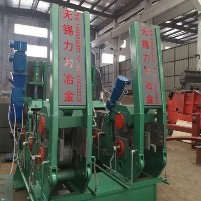
Evaluating a new system means looking hard at long-term reliability and daily maintenance. Mechanical systems fail because rotary bearings and pivot points wear out from friction. Advanced hydraulic systems ditch these moving parts. They use leaf spring guiding systems. Leaf springs flex without friction. They eliminate bearing play and force the mold to move strictly in the vertical axis with zero lateral deviation.
Hydraulic systems bring different maintenance demands. Reliability depends on fluid cleanliness and servo-valve integrity. Maintenance teams must run aggressive hydraulic fluid filtration. Microscopic dirt jams high-response proportional valves and causes erratic mold movement. Component lifespan goes up with hydraulic systems, but only if you maintain the hydraulic power unit to aerospace-level cleanliness standards. You have to flush the lines regularly and monitor accumulator pressures to keep the system responsive.
Retrofitting hydraulic oscillators into old plants is tough engineering. The physical footprint of the existing mold table and water jackets dictates your options. Hydraulic cylinders and manifolds need space. They often clash with secondary cooling headers or electromagnetic stirrers. You have to map out the entire mold housing before committing to a specific cylinder arrangement.
Structural rigidity is another massive factor. Hydraulic systems punch out intense, high-frequency forces. They will shake the casting floor structure to pieces if not isolated. Engineers must check the stiffness of the existing machine framework. Most retrofits require heavy steelwork reinforcement to handle the dynamic loads of a non-sinusoidal hydraulic oscillator. You also have to check cooling system compatibility. Hydraulic power units need dedicated heat exchangers to keep fluid viscosity stable during continuous casting.
Modern oscillation systems run on data. Upgrading the hardware is only part of the job. You have to integrate oscillation monitoring systems with Level 2 plant automation to see real gains. Modern hydraulic tables use high-resolution linear variable differential transformers (LVDTs) and multi-axis accelerometers. These sensors track the exact position and acceleration of the mold.
Real-time friction monitoring algorithms crunch this data to spot deviations from the target waveform. If a servo-valve sticks, or mold friction spikes from dry spots, the system catches it instantly. Operators get an early warning. They can drop the casting speed or intervene manually before the bad performance ruins the steel or causes a sticking breakout. Without this data integration, you are flying blind with expensive hardware.
Improper calibration is the biggest risk during installation. If the mold deviates from the absolute vertical axis during the stroke, it pushes laterally against the steel shell. This lateral movement wears out the copper plates unevenly. It puts asymmetrical stress on the solidifying strand, causing corner cracks and breakouts. Even a fraction of a millimeter of runout will destroy your surface quality.
Engineering teams must enforce strict laser alignment protocols during installation. Static alignment is never enough. You have to run extensive dynamic testing during commissioning. Use dummy bars and vibration analysis tools. Prove the mold tracks perfectly vertically under full hydraulic load at maximum frequencies. Do not sign off on the installation until the dynamic runout meets the strictest metallurgical tolerances.
Plants often ignore the human factor during equipment upgrades. Moving from fixed mechanical cams to dynamic hydraulic controls changes how operators cast steel. Operators used to setting a speed and walking away now have to understand waveforms, negative strip times, and stroke lengths. If they do not understand the physics, they will make the wrong adjustments during a crisis.
You have to retrain the floor crews. Build updated standard operating procedures that define acceptable parameter windows for every steel grade. Run simulator-based training. Let control room operators practice fixing simulated friction spikes or temperature drops using the new hydraulic interface. They need confidence before they take control of live liquid steel. A well-trained operator maximizes the value of mould oscillation continuous casting technology.
Rushing an installation guarantees commissioning delays and lost tons. You need a structured, data-driven approach. Before you cut out the old mechanical system, run extensive baseline testing. Record vibration signatures, flux consumption rates, and defect frequencies for a month of normal production. This baseline gives you hard performance benchmarks.
Once the new system goes in, execute a phased rollout.
Run initial casts using standard sinusoidal waveforms that mimic the old mechanical system.
Verify the basic hydraulic hardware functions correctly under thermal load.
Introduce complex non-sinusoidal waveforms on low-risk steel grades.
Activate dynamic stroke adjustments and compare surface quality against the historical baseline.
Roll out the optimized profiles to crack-sensitive and high-strength grades.
Audit the hydraulic fluid cleanliness after the first week of continuous operation.
With operations dating back to 1998, WUXI LIWEI METALLURGY EQUIPMENT CO., LTD specializes in metallurgical engineering design and general contracting, equipment design and manufacturing, installation, and commissioning. The company provides integrated solutions covering steel melting, continuous casting machines (CCM), and rolling mills, combining metallurgical engineering experience with equipment manufacturing and project implementation capabilities.
Initiate a comprehensive feasibility study focused on your specific product mix to determine the exact operational return of a hydraulic upgrade.
Request a structural audit of your current continuous casting machine framework to identify any retrofit bottlenecks or required steelwork reinforcements.
Consult with metallurgical equipment specialists to design a phased implementation roadmap that minimizes machine downtime.
Establish a baseline data collection protocol on your existing mechanical oscillators to measure post-upgrade surface quality improvements accurately.
A: Negative strip time is the specific duration during the mold's downstroke where the downward velocity of the mold exceeds the withdrawal speed of the steel strand. This relative motion compresses the solidifying shell, helps heal micro-tears, and pumps lubricating mold flux into the gap between the shell and the copper plates.
A: The oscillation cycle acts as a mechanical pump. The upward and downward strokes draw liquid flux into the mold-strand gap. The size and frequency of the resulting oscillation marks directly dictate consumption rates. Deeper marks entrap more flux and carry it down the mold, increasing overall powder consumption.
A: Deep oscillation marks are caused by excessive negative strip time, low oscillation frequencies, or excessively long stroke lengths. These parameters exert high compressive forces on the fragile meniscus. The pressure pushes the solidifying shell deeper inward, creating pronounced transverse depressions on the final steel surface.
A: Hydraulic oscillators allow for dynamic, on-the-fly adjustments to stroke length, frequency, and waveform without stopping the machine. They generate non-sinusoidal curves that optimize lubrication while minimizing negative strip time. This capability significantly improves surface quality, reduces breakout risks, and accommodates flying grade changes seamlessly.
A: Performance is monitored using high-resolution linear position sensors (LVDTs) and multi-axis accelerometers mounted directly on the mold table. This hardware feeds data into real-time friction monitoring systems. The automation detects abnormal performance, lateral deviations, or waveform distortions before they cause surface defects or breakouts.
A: As casting speed increases, the time available for the mold to overtake the strand decreases. To maintain an optimal negative strip time and prevent the shell from sticking to the copper plates, operators must generally increase the oscillation frequency proportionally with the casting speed.