
Views: 0 Author: Site Editor Publish Time: 2026-07-21 Origin: Site


Specifying a new billet caster involves high-stakes capital expenditure where precision engineering dictates plant profitability. Over-engineering the machine leads to wasted capital and excessive maintenance overhead. Under-engineering creates severe melt shop bottlenecks. Plant managers face significant operational friction when upstream furnace capacity, such as electric arc furnace (EAF) or basic oxygen furnace (BOF) tap-to-tap times, mismatches downstream casting throughput. This imbalance frequently results in aborted casts, excessive ladle temperature loss, and compromised steel quality. Resolving this bottleneck requires a strict technical evaluation framework. Determining the optimal continuous caster number of strands demands balancing target annual tonnage, billet cross-section, casting speed, and tundish fluid dynamics. By aligning these metallurgical and mechanical variables, melt shops can achieve seamless sequence casting and maximize overall yield.
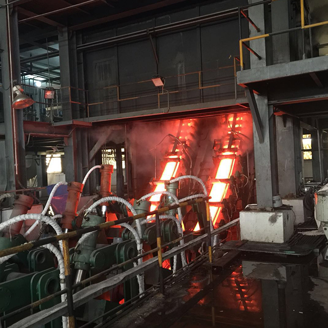
Throughput Matching: The exact number of strands must mathematically align with ladle capacity and maximum allowable ladle emptying time to prevent premature steel freezing.
Tundish Complexity: Increasing strand count exponentially complicates tundish fluid dynamics, requiring advanced flow control to ensure uniform temperature and inclusion flotation across all strands.
Speed vs. Strands: High-speed casting technologies (up to 7 m/min) can reduce the required number of strands for a given capacity, lowering equipment footprint and maintenance overhead.
CAPEX vs. OPEX: While fewer strands reduce initial machine costs and consumable spend, they require higher operational discipline to prevent breakouts from disrupting overall plant yield.
Table of Contents
Total caster throughput must equal or slightly exceed the output of the primary melting and secondary metallurgy units. This core equation drives the entire plant design. If the caster runs slower than the furnace tap-to-tap time, ladles queue up on the turret, losing critical superheat. If the caster outpaces the furnace, sequence casting breaks down, forcing turnaround times and reducing yield. You cannot afford to have a mismatch here. The entire rhythm of the melt shop depends on this synchronization.
The strand count directly dictates the ability to maintain continuous operation. Plant capacities range widely, from 300,000 to 2,500,000 tons per year. A facility targeting higher annual tonnage requires a machine configuration capable of absorbing large heat sizes without interrupting the steady state of the mold. Engineers calculate the required throughput by analyzing the liquid steel delivery rate and matching it against the maximum withdrawal speed of the combined strands. We look at the tap-to-tap time, usually around 40 to 50 minutes for a modern EAF, and ensure the caster can drain that ladle within the same window.
To illustrate the relationship between furnace output and caster configuration, consider the following baseline capacity metrics. These figures represent typical operational setups found in modern steelmaking facilities.
Annual Tonnage Target | Typical Heat Size | Required Caster Throughput | Typical Strand Count (Standard Speed) |
|---|---|---|---|
300,000 - 500,000 tpy | 40 - 60 tons | 60 - 80 t/h | 2 to 3 strands |
600,000 - 1,000,000 tpy | 80 - 120 tons | 100 - 150 t/h | 4 to 6 strands |
1,200,000 - 2,000,000+ tpy | 150 - 200+ tons | 200 - 300+ t/h | 8 to 12 strands |
Steelmakers operate within a strict thermal window. The critical threshold for ladle emptying time typically spans 45 to 60 minutes, depending heavily on initial superheat and ladle insulation quality. Extending cast times beyond this window introduces severe metallurgical risks. You will see temperature stratification in the ladle, premature freezing in the tundish nozzles, and severe clogging issues. Once the steel temperature drops near the liquidus line, castability plummets.
Calculating the optimal strand configuration relies on dividing the total ladle weight by the maximum per-strand throughput within this strict time constraint. For example, if a strand pulls up to 60 tons per hour, a 120-ton ladle requires at least two strands to empty within 60 minutes. However, operational realities, transition tonnage, and safety margins usually push the required count higher. You need a buffer. If one strand goes down for a dummy bar disconnect or a flying nozzle change, the remaining strands must be able to absorb the excess steel to prevent an aborted heat.
The metallurgical risks of extended casting times are not just theoretical. They manifest as hard operational failures on the cast floor. When steel sits too long, the temperature drops, and alumina inclusions begin to agglomerate. This leads to SEN (Submerged Entry Nozzle) clogging, which alters the fluid flow in the mold, causing uneven shell growth and eventual breakouts.
Standard-speed economic casters utilize conventional mold designs and secondary cooling profiles. They offer reliable operation but require more strands to handle a specific heat size. In contrast, high-speed advanced casting machines utilize optimized mold tapers, advanced hydraulic oscillation, and aggressive cooling to pull steel much faster. The choice between these two philosophies dictates the entire layout of your casting bay.
Choosing a standard speed over a high-speed configuration directly impacts the required machine width. A plant might need six standard strands to achieve an identical annual yield that four high-speed strands could accomplish. This decision shifts the balance between upfront mechanical footprint and the operational discipline required to run high-speed molds without breakouts. High-speed casting demands pristine water quality, exact mold alignment, and tight control over steel chemistry.
When evaluating these options, consider the following operational requirements for high-speed casting:
Implementation of advanced hydraulic oscillators to maintain precise negative strip times at high withdrawal speeds.
Utilization of parabolic or multi-tapered copper mold tubes to maintain contact with the shrinking steel shell.
Deployment of intensive secondary cooling zones with air-mist nozzles to extract heat rapidly without causing surface cracking.
Strict control of superheat at the ladle metallurgy furnace to ensure consistent steel fluidity.
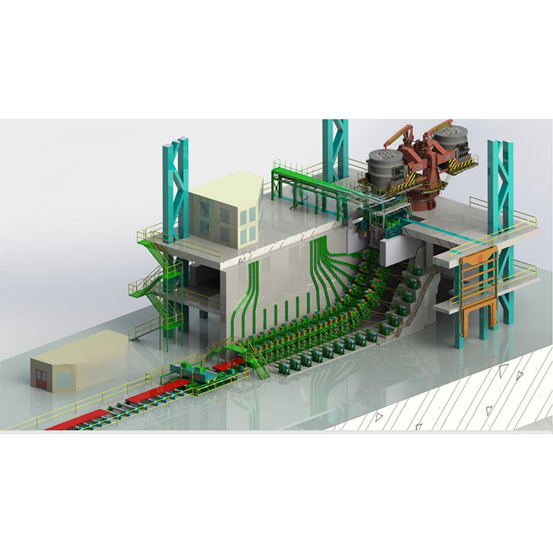
Mini-mills, specialty steel producers, and plants with small furnace capacities usually operate 20 to 40-ton ladles. These facilities benefit from low-capacity configurations featuring one to three strands. The primary advantage lies in a simplified tundish design. A smaller tundish minimizes refractory costs and simplifies fluid dynamics. You do not have to worry as much about dead zones or massive temperature drops across a long delta tundish.
These setups require lower initial capital expenditure and occupy a significantly reduced footprint. Maintenance crews easily access oscillation mechanisms and secondary cooling systems. The piping runs are shorter, the hydraulic units are smaller, and the overall mechanical complexity is manageable for a smaller maintenance team. They are ideal for economic caster setups with lower output requirements.
However, these machines remain highly vulnerable to complete production halts. If a single strand experiences a breakout or mechanical failure on a two-strand machine, the facility instantly loses fifty percent of its casting capacity. This often forces an aborted heat, sending tons of steel to the scrap yard. You lack the redundancy that larger machines inherently possess.
Standard commercial billet producers utilizing 60 to 120-ton ladles generally deploy four to eight strands. The standard six-strand billet caster model serves as the industry workhorse. This configuration perfectly balances transition tonnage and steady-state casting, allowing operators to absorb standard EAF output seamlessly. It provides enough capacity to handle the heat within the 50-minute window while offering enough redundancy to survive a single strand failure.
Design requirements for these machines emphasize symmetrical tundish designs. Managing velocity vectors becomes critical to ensure even steel distribution to the outer strands. Engineers must design the tundish to prevent dead zones and ensure the steel reaching strand one and strand six maintains the same temperature and inclusion cleanliness as the steel entering the inner strands. This often requires complex refractory furniture.
Operating a six-strand machine requires coordinated effort on the cast floor. The operators must manage mold levels across a wide physical area. The dummy bar insertion process must be synchronized, and the run-out area must be designed to handle a massive volume of hot billets simultaneously transferring to the cooling bed.
Mega-mills focusing on low-margin, high-volume commodity long products with large heat sizes (150+ tons) push the limits of caster design. These facilities deploy ultra-high volume configurations ranging from 9 to 12 strands. You see these setups in massive integrated plants or mega-mini-mills where throughput is the absolute priority.
The engineering requirements for these machines are staggering. They typically utilize radii ranging from 9 to 10 meters to accommodate the massive width of the strand layout. Technologies like Danieli Fast Cast configurations are often employed to manage the logistics of pulling that much steel simultaneously. The tundish alone can hold 40 to 50 tons of steel, acting as a massive reservoir to feed the widespread molds.
The challenges here revolve around extreme complexity. Dummy bar handling becomes a major logistical hurdle. Strand guide alignment across 12 independent lines requires dedicated maintenance teams working around the clock. The footprint required for the run-out area, cross-transfers, and cooling beds is massive. Furthermore, ensuring uniform steel temperature from strand 1 to strand 12 is a constant battle against thermodynamics.
The chosen strand count dictates tundish volume and shape. Single or twin-strand machines often use simple rectangular or delta shapes. As the count increases, designers shift to complex T-shapes to feed widespread molds. Computational fluid dynamics (CFD) plays a mandatory role in calculating transition tonnage and mapping velocity vectors at various locations in multi-strand tundishes. You cannot design a modern 8-strand tundish by guessing; you need hard data on how the steel flows.
CFD analysis often reveals stark differences between inner strands and outer strands. The steel reaching the outer nozzles has a longer residence time, leading to temperature drops and potential inclusion buildup. To ensure metallurgical uniformity, engineers install flow modifiers such as weirs, dams, and impact pads. These refractory components minimize dead zones, direct hot steel toward the outer nozzles, and promote inclusion flotation.
Proper tundish design ensures every billet meets quality specifications regardless of its position on the machine. We look at the residence time distribution (RTD) curves generated by the CFD models. The goal is to narrow the peak of the curve, ensuring that steel spends enough time in the tundish to float out alumina, but not so long that it loses critical superheat.
Billet cross-sections typically range from 80 to 175 millimeters square or round. An inverse relationship exists between this cross-section and the required casting speed. Smaller cross-sections must be cast faster to achieve the same mass throughput as larger sections. A 100x100mm billet must be pulled significantly faster than a 150x150mm billet to drain the ladle in the same amount of time.
High-speed casting capabilities push withdrawal rates up to 7 m/min, equivalent to up to 60 tons per hour per strand. Upgrading mold technology, including advanced copper tube tapers and intensive primary cooling, reduces the total number of strands required to meet annual capacity. However, the metallurgical length and the design of the secondary cooling zone ultimately limit the maximum achievable speeds.
The machine radius must support the complete solidification of the core before the billet reaches the unbending point. If you pull too fast, the liquid core extends past the unbending rolls, resulting in internal halfway cracks or, worse, a liquid core breakout on the run-out table. The following table illustrates the relationship between billet size and typical maximum casting speeds.
Billet Cross-Section (mm) | Standard Speed (m/min) | High-Speed Technology (m/min) |
|---|---|---|
100 x 100 | 3.0 - 3.5 | 5.0 - 7.0 |
130 x 130 | 2.2 - 2.8 | 3.5 - 4.5 |
150 x 150 | 1.8 - 2.2 | 2.8 - 3.5 |
Strand center distance defines the gap between adjacent molds, directly impacting the overall width of the casting machine. Wider center distances provide ample spatial requirements for segment rolls, spray headers, and maintenance access. Mechanics need physical room to safely extract jammed dummy bars, replace worn oscillation components, or change out secondary cooling manifolds. If you cram the strands too close together, maintenance becomes a nightmare.
Brownfield upgrades frequently face severe footprint constraints. Existing building columns, crane spans, and run-out tables limit the maximum width of the new machine. When physical space restricts the addition of more strands, plants must rely on higher casting speeds to meet increased furnace output. You have to work within the concrete boundaries of your existing melt shop.
Optimizing the strand center distance requires balancing operational access with structural limitations. A typical center distance for a billet caster ranges from 1000mm to 1400mm. Going narrower saves space but complicates the design of the oscillation tables and the spray cooling headers. Going wider increases the size of the tundish and the structural steel required for the casting floor.
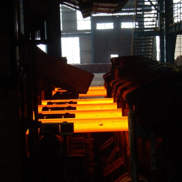
Adding strands requires evaluating the upfront cost against the compounding long-term operational expenditure of maintaining them. A wider machine demands a larger structural framework, more extensive hydraulic systems, and broader run-out tables. Beyond the initial build, every additional strand multiplies the daily consumable spend. You are buying more copper, more refractory, and more spare parts.
Maintenance teams must constantly replace copper mold tubes, submerged entry nozzles (SEN) or metering nozzles, dummy bar heads, and pinch rolls. Fewer strands running at higher speeds consolidate this wear, allowing maintenance budgets to focus on premium, longer-lasting components rather than spreading resources across eight or ten separate lines. It is often more cost-effective to maintain four high-performance strands than six mediocre ones.
Consider the daily maintenance tasks required for each active strand:
Inspection and replacement of copper mold tubes based on wear profiles.
Calibration of the mold level control sensors (radiometric or electromagnetic).
Verification of the hydraulic oscillator stroke length and frequency.
Cleaning and testing of the secondary cooling spray nozzles to prevent uneven cooling.
Multi-strand machines offer distinct operational flexibility. Operators can blind off a single strand for emergency maintenance while continuing to cast on the remaining strands. This redundancy prevents minor mechanical failures from causing complete heat aborts. If a dummy bar disconnects on strand three, you cap it, adjust the speed on the remaining strands, and finish the heat.
This flexibility also assists in managing fluctuating steel demand and varying ladle sizes. If the furnace delivers a short heat, operators can cap outer strands and finish the cast smoothly. This adaptability keeps upstream furnace operations running without forcing unscheduled downtime across the entire melt shop. You maintain the rhythm of the plant even when things go wrong.
Redundancy protocols must be established in the standard operating procedures. The cast floor team needs clear instructions on how to redistribute steel flow when a strand is lost. This involves adjusting the slide gate or stopper rod positions, modifying the casting speed, and ensuring the secondary cooling water curves adapt to the new withdrawal rates.
Consistent strand availability demands stringent reliability programs. Multi-strand machines increase the statistical probability of component failure simply by housing more moving parts. Plants must track critical components via Computerized Maintenance Management Systems (CMMS). You cannot rely on run-to-failure maintenance in a modern melt shop.
Maintenance records must monitor oscillation mechanisms, segment rolls, secondary cooling nozzles, and strand guide alignment. Predictive maintenance protocols, including vibration analysis on oscillators and regular alignment checks using specialized sleds, prevent unscheduled downtime and maintain product quality across all active lines. A misaligned strand guide will cause internal cracking and increase the breakout frequency.
A robust reliability program includes the following elements:
Routine laser alignment of the mold to the first zone segment.
Periodic water quality testing to prevent scale buildup in the mold cooling jackets.
Vibration monitoring of the pinch roll drives and oscillation tables.
Tracking the tonnage life of every copper mold tube to predict wear patterns.
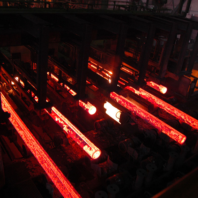
High-strand casters face the severe risk of outer strands receiving colder steel. This temperature stratification leads to premature freezing in the metering nozzles, strand loss, or inconsistent surface quality on the outer billets. When the steel loses superheat, its viscosity increases, altering the flow dynamics in the mold and compromising the lubrication provided by the mold powder or oil.
Mitigating this risk requires optimizing flow control furniture within the tundish to push fresh, hot steel outward. Additionally, plants deploy plasma tundish heating systems to maintain precise temperature control. Strict superheat management at the ladle metallurgy furnace (LMF) ensures the steel arrives at the caster with sufficient thermal energy to survive the extended residence time. You must deliver the steel to the caster at the exact right temperature.
High-speed, multi-strand casting inherently increases the severity and frequency of breakouts. If mold level control fluctuates or the hydraulic oscillator fails, the thin solidifying shell ruptures, spilling liquid steel into the machine and destroying segment rolls. A breakout on a high-speed machine is a violent event that causes significant equipment damage and hours of downtime.
Plants mitigate breakout risks by deploying advanced mold thermal monitoring systems utilizing dense thermocouple arrays or fiber optics. These systems feed data into automated breakout prediction algorithms, which instantly slow the casting speed if a sticker is detected. Precise hydraulic oscillators also ensure accurate negative strip times, preventing shell tearing at high withdrawal speeds. You need technology to catch the breakout before it happens.
Determining the correct machine configuration remains a strict mathematical derivation of ladle size, allowable casting time, and target billet dimensions. Melt shop logistics dictate the baseline requirements, while spatial constraints and maintenance capabilities refine the final design. Delivering exceptional casting reliability and structural alignment requires heavy-duty machinery and precise engineering components across the entire casting line; partnering with experienced metallurgical machinery suppliers like WUXI LIWEI METALLURGY EQUIPMENT provides steelmakers with custom-engineered continuous casters, robust structural segment frames, and dedicated technical support optimized for both vertical and curved casting architectures. Decision-makers should prioritize high-speed casting technologies to minimize strand count where possible, thereby reducing mechanical complexity and consumable spend.
Commission a comprehensive melt shop logistics simulation to map tap-to-tap times against withdrawal rates.
Execute tundish CFD modeling to verify temperature uniformity across the proposed strand count.
Consult with original equipment manufacturers to evaluate high-speed mold technologies.
Audit existing maintenance capabilities to ensure the team can support the required oscillation and alignment tolerances.
A: Modern high-capacity billet casters can be configured with up to 12 strands. These massive machines are typically utilized in mega-mills to process very large heat sizes and achieve capacities up to 2,500,000 tons per year.
A: Divide the total ladle weight by the product of the maximum allowable casting time and the target throughput per strand. The result must be rounded up to ensure the ladle empties completely before the steel temperature drops below critical thresholds.
A: Higher casting speeds, reaching up to 7 m/min, increase the throughput per strand up to 60 tons per hour. This efficiency allows a plant to achieve the same annual tonnage with fewer strands, reducing the machine footprint and maintenance costs.
A: Billet casters specifically produce solid steel strands that are typically 80 to 175 millimeters square or round. These dimensions serve as the standard feedstock for downstream rolling mills producing rebar, wire rod, and light structural shapes.
A: Outer strands sit furthest from the ladle shroud impact zone. Steel loses heat as it travels through the tundish, causing temperature stratification. Without proper flow modifiers, the steel reaching the outer nozzles drops below the required superheat, causing freezing.


