Views: 0 Author: Site Editor Publish Time: 2026-09-28 Origin: Site


Plant managers and investors face intense pressure to configure mini-mill setups that balance high initial capital expenditure with long-term operational efficiency, strict metallurgical quality, and modern safety standards. Moving away from traditional integrated blast furnace routes requires a hard look at advanced electric steelmaking. Successfully deploying the EAF LF CCM process demands rigorous evaluation of equipment specifications, raw material availability, facility infrastructure, and digital readiness. This guide breaks down the technical evaluation criteria, implementation risks, and return on investment factors for modernizing or establishing a new steelmaking facility. You will learn how to optimize equipment selection, mitigate operational bottlenecks, and achieve the exact metallurgical properties required for your target product mix without relying on outdated methodologies. We evaluate the core components, layout considerations, and automation requirements that dictate plant performance.
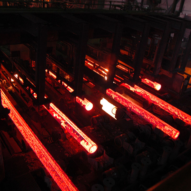
Process Synergy: The EAF LF CCM process separates melting (EAF) and refining (LF) to optimize tap-to-tap times, allowing the Continuous Casting Machine (CCM) to operate at maximum yield and sequence length.
Metallurgical Control: Integrating a Ladle Furnace is non-negotiable for producing high-quality, low-alloy, or special steel grades, as it ensures precise temperature homogenization, inclusion floatation, and exact chemistry adjustments.
Infrastructure Dependency: Viability heavily depends on local electrical grid stability, requiring robust power quality mitigation (e.g., Static Var Compensators) to handle EAF-induced grid flicker and harmonics.
Decarbonization Leverage: When paired with direct reduced iron (DRI) and renewable energy grids, this route offers a significantly lower carbon footprint compared to the BF-BOF route, directly impacting compliance and carbon tax liabilities.
Industry 4.0 Integration: Modern setups rely heavily on Level 2 and Level 3 automation, digital twins, and predictive maintenance to minimize downtime and optimize consumable usage.
Table of Contents
Understanding the distinct phases of electric steelmaking dictates plant layout and operational pacing. Each unit operation must perform its specific function without overlapping duties to maintain high throughput. The separation of melting, refining, and casting allows operators to run concurrent batches, maximizing the utilization of electrical infrastructure and heavy lifting equipment.
The EAF rapidly melts scrap iron or direct reduced iron. You need to select feeding methods based on workshop layout and scrap handling. Traditional bucket feeding opens the furnace roof, causing major heat loss, nitrogen contamination and interrupted melting cycles. Continuous feeding systems like Consteel or Quantum EAF use vibrating conveyors to feed scrap into molten steel in a sealed furnace, recovering waste gas heat to preheat scrap and smoothing power load on the grid. Operators balance electric power from graphite electrodes and chemical energy from oxygen, carbon and oxy-fuel burners; more chemical energy cuts grid power consumption and speeds melting. Standard melting steps include scrap loading, arc start-up, main melting, foamy slag formation and steel tapping while keeping residual hot metal for the next batch. Foamy slag made by injecting carbon and oxygen covers the electric arc, sending heat into molten steel instead of the water-cooled furnace lining. This improves heat efficiency, lowers noise and extends lining life. The EAF should only melt raw materials; doing refining work inside it lengthens cycles, wastes power and quickly damages furnace lining.

After crude molten steel flows out from the EAF, the ladle furnace carries out refining. The oxidizing environment inside the EAF cannot remove sulfur, while the LF creates a reducing atmosphere for deep sulfur removal, deoxidation and accurate alloy mixing. Without an LF, only simple rebar can be produced. Workers add custom blended synthetic slag of lime, alumina and fluorspar to absorb non-metallic impurities floating from molten steel, avoiding nozzle blockage during casting and meeting strict steel cleanliness requirements. Argon gas injected through bottom porous plugs stirs liquid steel to balance temperature and chemical composition and speed impurity separation; top lances serve as backup if bottom plugs wear out. The LF also works as a temperature and timing buffer, matching the fast batch tapping cycles of the EAF with the steady continuous operation of the CCM.
The CCM turns molten steel into solid billets, blooms or slabs. Steel transferred from ladle to tundish must be shielded from air to stop reoxidation. The tundish stores and distributes molten steel and uses internal flow baffles to guide steel upward so impurities float into the covering flux before steel enters the copper mold. Vertical oscillation of the copper mold quickly cools steel to form a solid outer shell and prevents sticking; negative strip time fixes tiny cracks to avoid steel breakout. Air-mist secondary cooling zones under the mold follow grade-specific cooling curves to prevent surface cracks and internal stress defects. Electromagnetic stirring (EMS) stirs the liquid core of the solidifying steel strand to form uniform grain structure, and Dynamic Soft Reduction (DSR) squeezes the strand at final solidification to remove residual liquid steel and eliminate center segregation, greatly improving internal quality for high-performance steel products.
Facility design requires aligning equipment capabilities with market demands, utility constraints, and raw material logistics. A mismatch in any of these areas leads to operational bottlenecks, excessive downtime, and reduced profitability. You must evaluate the macro-level inputs before finalizing any equipment specifications.
Match your equipment setup to the steel types you plan to manufacture. Basic EAF and LF with simple automation work for common rebar, but automotive flat steel, wire rod and special bar quality steel need advanced secondary refining. Premium steel products require tight limits on nitrogen, hydrogen and oxygen, which may call for extra specialized gear. Vacuum degassing (VD) or vacuum oxygen decarburization (VOD) units are needed for ultra-low carbon steel, bearing steel and hydrogen-free heavy forgings, since standard ladle furnaces cannot remove enough dissolved gas. Adding VD equipment needs taller workshop space, dedicated steam ejector pumps and an independent cooling water system.
Calculate required power based on your target hourly output. Electric steelmaking uses large amounts of energy, consuming 380–450 kWh per ton of molten steel. A mini-mill needs a large, stable power supply, so you must check the local grid’s short-circuit capacity. The short-circuit ratio (SCR) between grid power and EAF transformer size defines electric stability; an SCR below 50 means the grid is too weak to reliably run an EAF. Unstable electric arcs create voltage flicker and waveform distortion, which can trigger fines or power cut-offs from utility providers. SVC or STATCOM systems fix these power quality problems, meet grid rules, stabilize voltage at the furnace and raise usable power delivered to the EAF.
Check local scrap availability, density and price swings. Scrap is the main feedstock but quality varies greatly. Low-density shredded scrap melts fast yet needs multiple bucket loads, increasing furnace downtime. Heavy melting scrap (HMS) has higher density but melts slower and needs more oxygen injection. Ordinary scrap holds unwanted impurity metals including copper, tin and nickel, which do not burn away during melting and lead to cracking during hot rolling. To make high-grade steel, mix scrap with pure iron materials to dilute these harmful impurities.
Raw Material Type | Density (t/m3) | Tramp Element Content | Impact on EAF Operation |
|---|---|---|---|
Heavy Melting Scrap (HMS) | 0.8 - 1.2 | Moderate to High | Requires longer melting time; good for bath density. |
Shredded Scrap | 1.0 - 1.4 | Moderate | Fast melting; requires multiple charges if used exclusively. |
Direct Reduced Iron (DRI) | 1.6 - 1.9 | Very Low | Dilutes tramp elements; increases slag volume due to gangue. |
Hot Briquetted Iron (HBI) | 2.4 - 2.8 | Very Low | Excellent density; sinks into bath easily; ideal for high-end grades. |
Assess the facility's capacity for IoT sensor integration. Modern steelmaking relies on continuous data acquisition to optimize the EAF–LF–CCM Steelmaking Process. Continuous temperature monitoring systems and real-time off-gas analysis provide feedback loops. Off-gas analysis measures carbon monoxide, carbon dioxide, and oxygen in the exhaust duct, allowing automated adjustments to burner and lancing profiles to maximize chemical energy recovery.
Evaluate data infrastructure required for predictive maintenance models. Critical components, such as EAF transformers, hydraulic systems, and water-cooled panels, require constant condition monitoring. Vibration sensors and thermal imaging feed data into predictive algorithms. This allows maintenance teams to replace components during scheduled downtimes rather than facing catastrophic mid-heat failures that freeze liquid steel in the ladles.
Selecting the right equipment dictates the operational ceiling of your plant. You must weigh the technical features against the tangible outcomes they produce on the shop floor. Over-specifying equipment wastes capital, while under-specifying creates permanent production bottlenecks.
Ultra-high power (UHP) transformers provide higher secondary voltage to support long-arc melting. This setup delivers more power, keeps electrodes above the molten steel, cuts electrode wear and limits unwanted carbon mixing into steel. Larger transformer capacity shortens the full melt cycle, raises daily output and reduces fixed cost per ton. High-power operation needs strong water-cooled panels, high-flow cooling circuits and reliable heat-resistant lining to handle strong heat radiation from long electric arcs.
High-performance ladle furnaces reach a heating speed of 3–5°C per minute, supported by responsive hydraulic electrode control that keeps stable arcs without adding extra carbon or creating heavy slag splashing. Accurate heating controls the steel’s extra heat above melting point (superheat) within a narrow 10°C range for smooth continuous casting. If the temperature is too low, steel solidifies early and blocks the intermediate vessel nozzle; if too hot, the thin solid steel shell breaks and causes serious equipment damage and long production stops.
Vertical-bending casters let non-metal impurities rise before the steel strand bends, making cleaner steel for automotive products, while curved casters need lower building height to save construction cost but mainly work for ordinary steel grades. Advanced sensors keep molten steel level steady within millimeters inside the mold. Combined with automatic dynamic cooling, this reduces surface cracks and oscillation marks, improves finished steel quality and lowers extra surface rework.
Robots handle sampling, temperature checks and tapping instead of manual work, protecting workers from intense heat and flying slag. Robotic tools deliver consistent, accurate data for the plant’s Level 2 automation system. Robotic systems move workers away from dangerous high-temperature areas to boost safety. Automatic EBT sand filling and tapping help transfer steel without slag, preserve alloy yield, prevent phosphorus contamination and keep steel clean.
Process Phase | Critical Equipment | Primary Function | Key Operational Outcome |
|---|---|---|---|
Melting (EAF) | UHP Transformer & Chemical Burners | Rapid liquefaction of scrap/DRI | Minimized tap-to-tap time |
Refining (LF) | Electrode Regulation & Porous Plugs | Desulfurization and temperature control | Exact superheat and chemical composition |
Casting (CCM) | Oscillating Copper Mold & EMS | Controlled solidification of liquid steel | Defect-free billets with high prime yield |
Grid Mitigation | STATCOM / SVC | Reactive power compensation | Utility compliance and stable busbar voltage |
Building or upgrading a steel plant involves navigating complex financial trade-offs. Upfront capital expenditure heavily influences long-term operational expenditure. You must model these trade-offs over a 15-to-20-year equipment lifecycle to understand the true cost of production.
Closed-loop automation and continuous scrap feeding systems demand higher initial spending and structural upgrades, unlike conventional bucket-charged EAFs with lower startup cost but greater electricity and graphite electrode use per ton of steel. Continuous feeding cuts power use to under 380 kWh per ton, balances grid load and reuses waste gas heat to preheat scrap; over ten years of large-scale production, the ongoing energy savings easily offset the higher upfront construction cost and help resist energy price swings.
Graphite electrodes are a major recurring expense, and well-run plants aim to keep electrode consumption under 1.5 kg per ton. Unstable arc control, heavy oxidation and repeated furnace roof lifting will push electrode usage higher and eat into profits. Standard heat-resistant lining bricks cost less upfront but need frequent repair and full replacement, leading to more production downtime. Premium magnesia-carbon bricks cost more at purchase but stand up better to slag erosion and temperature changes, supporting longer production runs, more continuous casting cycles and higher annual output.
Primary and secondary dust extraction systems including baghouses, water-cooled pipes and exhaust fans need large capital investment and power consumption to meet strict dust limits below 5 mg/Nm³. Investing in these emission control systems can avoid regulatory shutdowns and heavy fines, and the return can be calculated against carbon credits and penalties. Low-emission operation also improves community acceptance, simplifies permit approval in strictly regulated regions and helps the plant earn price premiums for green steel products.
Commission a bankable feasibility study focusing on local scrap availability, grid capacity, and a detailed lifecycle analysis before initiating vendor RFQs.
Execute a comprehensive grid impact study with your local utility provider to determine exact STATCOM or SVC requirements for your specific transformer ratings.
Develop a strict pacing model using Level 2 automation software to synchronize EAF melting, LF refining, and CCM casting cycles to prevent sequence breaks.
Initiate vendor RFQs prioritizing OEMs with proven safety robotics, closed-loop automation capabilities, and localized support for consumable supply chains.
A: Modern Ultra-High Power Electric Arc Furnaces achieve tap-to-tap times of 35 to 50 minutes. This rapid cycle is possible because the EAF functions solely as a melting unit. The Ladle Furnace takes over the time-consuming refining and alloying phases, allowing the EAF to immediately begin melting the next scrap charge.
A: The EAF route utilizes electricity to melt recycled steel scrap or DRI, offering a smaller footprint, lower capital costs, and high operational flexibility. The Blast Furnace-Basic Oxygen Furnace route relies on iron ore and coal, requiring massive scale. The EAF route produces significantly lower carbon emissions.
A: Using the EAF for metallurgical refining wastes electrical energy, drastically increases tap-to-tap time, and severely damages furnace refractories. The LF provides a controlled, reducing environment necessary for precise alloying, deep desulfurization, inclusion removal, and exact temperature control before continuous casting.
A: The primary consumables include graphite electrodes for arc generation, magnesia-carbon refractory bricks for furnace linings, and oxygen or natural gas for chemical energy. Other consumables include synthetic slag mixtures, argon gas for stirring, continuous casting mold powders, and the copper molds used in the CCM.
A: Yes, this process readily produces high-quality automotive and special bar quality steels. Producing these grades requires high-quality, low-residual scrap or virgin iron units like DRI to limit tramp elements. It also requires advanced LF refining and often vacuum degassing to remove dissolved gases.