
Views: 0 Author: Site Editor Publish Time: 2026-08-17 Origin: Site


Unplanned yield loss, escalating surface conditioning expenses, and downstream rolling failures directly hit the bottom line of any steelmaking operation. At the core of these operational inefficiencies lies the challenge of managing continuous casting billet defects. Diagnosing these flaws is notoriously complex. Multiple process variables—ranging from molten steel chemistry and casting speed to mould oscillation dynamics and secondary cooling intensity—interact simultaneously. When a defect appears on the cooling bed, isolating the exact root cause requires cutting through a web of overlapping parameters.
You cannot fix what you do not systematically understand. Addressing these metallurgical and mechanical anomalies requires a structured framework. By accurately categorizing defects, evaluating their underlying metallurgical mechanisms, and assessing targeted equipment upgrades, plant operators can achieve strict quality compliance. This guide provides a technical evaluation of common defects, bridging the gap between theoretical metallurgy and practical machine operation.
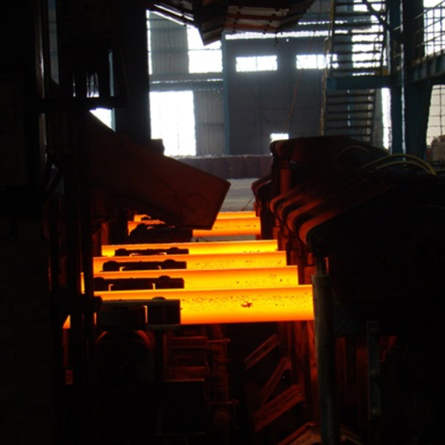
Continuous casting billet defects are systematically categorized into three primary areas: surface defects, internal defects, and shape (geometric/appearance) deviations.
Surface and shape defects (like rhomboidity, missing squares, and longitudinal cracks) are predominantly driven by primary cooling anomalies in the copper mould tube and uneven heat transfer.
Internal defects (such as central shrinkage and diagonal cracking) require interventions in the secondary cooling zone and the application of electromagnetic stirring (EMS).
Evaluating equipment upgrades requires balancing capital expenditure against the operational scalability of automated cooling controls and advanced mould oscillation systems.
Table of Contents
Before adjusting machine parameters, operators must define the baseline quality requirements for the specific downstream application. Success criteria vary wildly depending on the final product. Billets intended for standard commercial rebar can tolerate minor surface imperfections that will scale off during reheating. Conversely, billets destined for seamless pipe manufacturing, wire rod, or cold-heading applications demand near-zero defect tolerances. Establishing these acceptable defect thresholds prevents over-engineering the solution while protecting downstream yield.
To streamline troubleshooting on the melt shop floor, we group defects into three macro-categories. Identifying the category immediately narrows down the problematic zone within the continuous casting machine (CCM). When you walk the cooling bed and identify a specific flaw, you can trace it back to a specific machine zone.
Surface Defects: These originate almost exclusively in the copper mould tube (primary cooling zone) or at the meniscus. They point directly to issues with mould powder lubrication, oscillation settings, or initial heat transfer rates.
Internal Defects: These develop deeper within the strand as it moves through the secondary cooling and unbending zones. They indicate problems with spray cooling intensity, mechanical roll support, or overall metallurgical length.
Shape Defects: These geometric deviations occur when the solidifying shell experiences uneven thermal contraction or mechanical distortion. This usually starts in the mould and worsens as the strand passes through the withdrawal straightening unit (WSU).
A strict baseline assumption applies to all mechanical troubleshooting: melt shop parameters must be controlled first. You cannot fix bad steel chemistry with good machine settings. Tramp elements like copper, tin, and antimony accumulate at the grain boundaries during solidification, causing hot shortness. Elevated sulfur and phosphorus content, combined with excessive tundish superheat, drastically lowers the high-temperature ductility of the steel. If the chemistry falls outside specification, the solidifying shell will crack regardless of how perfectly the casting machine operates. Operators must maintain a high Manganese-to-Sulfur (Mn/S) ratio to prevent sulfur-induced cracking before looking at mechanical faults.
Longitudinal and transverse cracks represent some of the most common and damaging surface discontinuities. Longitudinal cracks run parallel to the casting direction, while transverse cracks run perpendicular. The root causes almost always trace back to uneven primary cooling, improper mould taper, or excessive friction between the solidifying shell and the copper mould wall. When heat transfer is non-uniform, the shell develops localized thin spots. As the steel shrinks, tensile stresses concentrate in these weak areas, tearing the fragile shell apart.
The metallurgical realities of the meniscus—the interface between the liquid steel, the mould powder, and the copper wall—dictate crack formation. Stress concentrations peak here. Deep oscillation marks, caused by improper negative strip time, act as stress raisers. Transverse cracks frequently initiate at the root of these deep oscillation marks and propagate as the strand bends in the machine.
Mitigation requires absolute precision in the mould. Operators must implement automated mould level control to keep the meniscus stable within a tolerance of ±3 millimeters. Furthermore, optimizing casting powder viscosity ensures a uniform lubricating film between the shell and the mould. The powder must melt at the correct rate to match the casting speed, reducing friction and evening out heat transfer across the copper faces.
Corner cracks typically occur when the corners of the billet overcool in the mould. Because corners dissipate heat in two directions simultaneously, they solidify faster than the flat faces. If the mould taper is too aggressive or the primary cooling water velocity is too high, the corners become brittle and pull away from the mould wall. This loss of contact causes reheating and subsequent tearing. Pinholes, on the other hand, are small cavities on the surface caused by dissolved gases—specifically hydrogen, nitrogen, and oxygen—precipitating out of the molten steel during rapid solidification.
Evaluating these issues requires looking upstream at ladle metallurgy. Operators must assess the trade-offs between different deoxidation practices. Strong deoxidation with aluminum reduces oxygen pinholes but increases the risk of solid alumina inclusions clogging the submerged entry nozzle (SEN). Balancing deoxidation with calcium treatment modifies the inclusions into liquid calcium aluminates, providing the cleanest surface results without restricting nozzle flow. To prevent nitrogen pinholes, operators must ensure perfect argon shrouding between the ladle and the tundish.
Slag entrapment occurs when liquid mould flux is pulled down into the solidifying steel shell. This is primarily driven by severe mould level fluctuations or an improper SEN immersion depth. If the SEN is too shallow, the steel jets disturb the meniscus, tearing the slag layer and dragging particles into the melt. If the casting speed changes abruptly, the resulting turbulence creates the exact same entrainment effect.
The impact on yield is severe. Billets with trapped slag or heavy surface inclusions cannot be rolled directly into finished products. They require heavy surface scarfing or mechanical grinding to remove the defects. This conditioning process directly reduces operational yield, consumes manual labor, and delays production schedules. Maintaining a steady casting speed and a constant SEN immersion depth of 100 to 150 millimeters prevents meniscus turbulence.
Cold shuts and pouring joints manifest as severe surface discontinuities that look like deep seams or folds. They are caused by interruptions in the pouring process, drastic mould level drops, or excessively low casting temperatures. When the molten steel level drops and then rises again, or when the steel is too cold, the meniscus freezes prematurely. The newly poured liquid steel fails to fuse completely with this solidified ring, creating a weak mechanical joint.
Mitigating cold shuts relies on maintaining a continuous, fluid meniscus. This highlights the absolute necessity of automated mould level regulation systems equipped with radioactive or electromagnetic sensors. Additionally, strict tundish temperature control must be enforced. The steel must arrive at the mould with adequate superheat—typically 25°C to 35°C above the liquidus temperature—to prevent premature freezing at the mould wall.
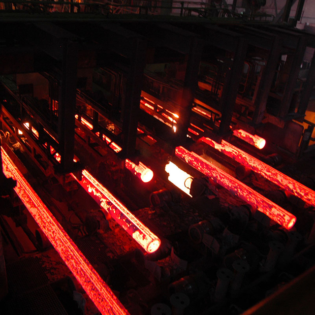
Internal defects remain hidden until the billet is sectioned or rolled, making them particularly insidious. Central shrinkage and porosity occur due to the natural volume contraction of steel as it transitions from liquid to solid. During the final stages of solidification in the unbending zone, the liquid core is cut off from the feeding liquid above. As this isolated pocket freezes, it shrinks, leaving behind a central void or a network of porous holes.
Mitigation depends on matching the casting speed to the machine's cooling capacity to maintain a proper metallurgical length. The point of final solidification must occur before the billet is completely severed at the torch cutter. Applying soft reduction—a slight mechanical compression of the billet using the WSU rolls just before final solidification—can physically squeeze the remaining liquid into the shrinkage voids, closing them entirely.
Intercolumnar and diagonal cracks form deep within the billet structure. They are driven by mechanical stresses applied to the strand during the transition from the mould to the secondary cooling zone. If the solidifying shell is too thin or the strand support rolls are misaligned, the ferrostatic pressure of the liquid core causes the billet faces to bulge outward. This bulging creates massive internal tensile stresses, tearing the fragile structure between the growing columnar dendrites.
Linking these features to outcomes requires evaluating the precision of the secondary cooling spray distribution. Uneven cooling causes thermal shocks, which exacerbate internal tearing. Ensuring perfect alignment of the strand support rolls and maintaining a smooth, gradual cooling curve are non-negotiable steps for preventing diagonal cracks. Operators must regularly check the roll pitch to ensure it adequately supports the shell against ferrostatic pressure.
Unlike surface pinholes, internal blowholes are larger gas cavities trapped deep within the billet cross-section. They severely compromise the structural integrity of the final rolled product, often leading to splitting during the rolling process. The root causes trace back to inadequate deoxidation in the ladle furnace and high moisture content in the raw materials, refractory linings, or casting powders. Moisture breaks down at high temperatures, injecting hydrogen directly into the melt.
Mitigation requires strict moisture control protocols. All tundish boards, nozzles, and casting powders must be kept in climate-controlled environments and preheated before use. Secondary metallurgy practices must ensure total oxygen and hydrogen levels are reduced to absolute minimums before the ladle opens over the tundish. Hydrogen levels should strictly remain below 3 parts per million (ppm) to prevent internal blowhole formation.
A perfect billet should have a perfectly square cross-section. Rhomboidity occurs when the cross-section distorts into a diamond shape. Off-squareness, often referred to as missing squares, happens when one or more corners fail to form a strict 90-degree angle. The root cause is the uneven growth of the solidifying shell inside the mould. This asymmetrical cooling is frequently caused by worn copper mould tubes that have lost their internal taper, or by misaligned cooling water jackets that create uneven water velocity around the tube.
The operational risk of severe rhomboidity is high. Distorted billets do not track straight. They lead to severe jamming in the withdrawal and straightening unit. Furthermore, when these misshapen billets reach the rolling mill, they cause feeding issues, twist in the roughing stands, and frequently result in cobbles that halt the entire rolling line. Operators must monitor the temperature difference (Delta T) of the mould cooling water across all four faces to detect asymmetrical heat transfer early.
Bulging occurs when the flat faces of the billet bow outward, while concavity is the inward sinking of the faces. Both defects stem from a mismatch between the strength of the solidifying shell and the ferrostatic pressure exerted by the liquid core. Insufficient strand support immediately below the mould allows the shell to bulge. Conversely, if the secondary cooling is too intense, the rapid thermal contraction pulls the faces inward, causing concavity.
To mitigate these geometric deviations, operators must evaluate the necessity of rigid foot rollers attached directly to the bottom of the mould assembly. These rollers provide critical mechanical support during the most vulnerable stage of shell growth. Optimized spray cooling intensity immediately below the mould must be calibrated to cool the shell evenly without causing drastic thermal shrinkage. The specific water flux must match the steel grade's thermal conductivity.
Longitudinal twisting and bending result in billets that look like corkscrews or curved bows. This makes them nearly impossible to stack, transport, or feed into a reheat furnace. The primary root cause is uneven secondary cooling across the four faces of the billet. If the top face cools faster than the bottom face, the billet will bend upward. Mechanical misalignment or uneven pressure applied by the drive rolls in the WSU also forces the strand out of alignment.
Routine mechanical alignment audits are the best mitigation strategy. Maintenance teams must regularly calibrate the WSU roll pressures to ensure symmetrical force application. Additionally, secondary cooling spray nozzles must be inspected and cleaned weekly. Clogged nozzles create dry spots on the billet surface, guaranteeing asymmetrical heat removal and subsequent twisting.
Defect Troubleshooting and Root Cause Matrix
Defect Category | Specific Defect | Primary Root Cause | Target Mitigation Zone |
|---|---|---|---|
Surface | Longitudinal Cracks | Uneven mould heat transfer, poor lubrication | Copper mould tube, flux viscosity |
Surface | Slag Entrapment | Mould level fluctuations, SEN depth | Meniscus control, auto-level systems |
Internal | Central Shrinkage | Volume contraction, incorrect casting speed | Secondary cooling, unbending zone |
Internal | Diagonal Cracking | Mechanical bulging, thermal shock | Support rolls, spray distribution |
Shape | Rhomboidity | Worn mould taper, uneven water jacket | Primary cooling hardware maintenance |
Shape | Longitudinal Twisting | Clogged spray nozzles, WSU misalignment | Secondary cooling headers, drive rolls |
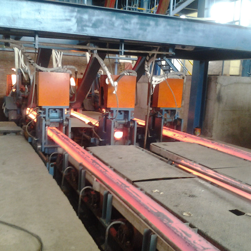
The mould oscillation system dictates surface quality. When evaluating upgrades, plants must compare traditional mechanical (cam-driven) oscillators against modern hydraulic systems. Mechanical systems operate on a fixed stroke and frequency, which limits flexibility when casting different steel grades or changing speeds. You are locked into a single oscillation profile regardless of what the steel chemistry demands.
Hydraulic oscillation systems offer superior scalability and control. They allow operators to make on-the-fly adjustments to stroke length and frequency. This capability is required for optimizing negative strip time—the brief period where the mould moves downward faster than the casting speed. Perfecting negative strip time (usually targeting -20% to -30%) minimizes the depth of oscillation marks, directly reducing the incidence of transverse cracks and surface tearing.
The secondary cooling zone manages the thermal profile of the billet as it solidifies entirely. Assessing cooling solutions usually comes down to air-mist cooling versus conventional water spray systems. Conventional water sprays often create localized cold spots where the water hits the steel, leading to severe thermal gradients and surface reheating when the water boils off.
Air-mist cooling mixes compressed air with water to atomize the droplets. This provides a much wider, more uniform cooling footprint. The outcome is a drastic reduction in the thermal shocks that lead to diagonal and intercolumnar cracking. Furthermore, air-mist systems allow for a wider turndown ratio, giving operators finer control over cooling intensity across varying casting speeds and steel grades.
Electromagnetic stirring uses magnetic fields to induce fluid flow within the unsolidified liquid core of the strand. Evaluating EMS requires analyzing the high capital cost of installation against the long-term return on investment. Mould EMS (M-EMS) rotates the liquid steel in the mould, washing away trapped gases and inclusions from the solidification front, thereby improving surface quality and reducing pinholes.
Strand EMS (S-EMS) is installed lower down the machine. It breaks up growing columnar dendrites, promoting an equiaxed crystal structure in the center of the billet. This conceptual trade-off involves higher energy consumption and specialized maintenance. However, the direct reduction in internal defect rejection rates—specifically the elimination of central shrinkage and severe porosity—often justifies the investment for high-quality steel producers manufacturing seamless pipes or bearing steels.
Upgrading equipment is only half the battle; the implementation risks lie in parameter tuning. There is a significant danger in implementing aggressive cooling profiles without accounting for crack-sensitive steel grades. For example, peritectic steels (carbon content between 0.09% and 0.17%) undergo a massive volume contraction during phase transformation. If cooled too rapidly, they will suffer catastrophic longitudinal cracking.
To mitigate this, plants must utilize dynamic cooling models. These software systems adjust spray intensity automatically based on real-time inputs, including casting speed, tundish temperature, and the specific steel grade chemistry. Relying on static cooling curves for diverse product mixes guarantees inconsistent quality and high rejection rates.
The copper mould tube is the heart of the casting machine. The greatest adoption risk is the operational failure of running these tubes beyond their designed lifespan. As thousands of tons of steel pass through, the copper wears down, losing its internal taper. This loss of geometry leads directly to rhomboidity, missing squares, and eventually, dangerous liquid steel breakouts.
Establishing strict predictive maintenance schedules is mandatory. Maintenance teams must perform regular dimensional checks using specialized taper gauges rather than relying solely on tonnage cast. Furthermore, the cooling water jackets surrounding the tubes must undergo routine descaling. Scale buildup acts as an insulator, destroying the heat transfer efficiency and causing the copper tube to warp under thermal stress.
To immediately improve billet quality and reduce rejection rates, execute the following steps:
Conduct a comprehensive metallurgical audit of currently rejected billets to map the exact defect types and their frequency.
Execute a full mechanical alignment check of the continuous casting machine, focusing on the mould water jackets and the withdrawal straightening unit.
Implement a strict, measurement-based replacement schedule for all copper mould tubes based on taper loss rather than just tonnage cast.
Calibrate secondary cooling spray nozzles weekly to ensure symmetrical heat removal across all billet faces.
Consult with continuous casting equipment specialists to evaluate the feasibility of integrating hydraulic oscillation and air-mist cooling systems.
From Defect Control to Complete Continuous Casting Solutions
For steel plants seeking to improve billet quality through both process optimization and equipment upgrades, WUXI LIWEI METALLURGY EQUIPMENT CO., LTD provides integrated metallurgical engineering, equipment manufacturing, installation, commissioning, and turnkey solutions covering steel melting, continuous casting machines, and rolling mills. With operations dating back to 1998 and project cooperation with more than 300 companies across multiple international markets, the company brings practical continuous casting and system-integration experience to billet quality improvement projects.
A: Rhomboidity and missing squares are caused by uneven growth of the solidifying shell inside the mould. This uneven cooling is typically the result of worn copper mould tubes that have lost their taper, misaligned cooling water jackets, or asymmetrical water flow. As the shell shrinks unevenly, the billet distorts into a diamond shape or loses its 90-degree corners.
A: Longitudinal cracks are prevented by ensuring uniform primary cooling, maintaining correct mould taper, and optimizing casting powder viscosity to reduce friction. Pouring joints are mitigated by maintaining a continuous, stable mould level using automated regulation systems and ensuring the molten steel retains adequate superheat to prevent premature freezing at the meniscus.
A: Secondary cooling controls the thermal gradient of the billet as the liquid core solidifies. If cooling is uneven or too aggressive, it causes thermal shock and mechanical bulging, leading to internal diagonal and intercolumnar cracks. Optimized, uniform secondary cooling ensures a smooth temperature drop, minimizing internal tensile stresses.
A: Pinholes and blowholes form when dissolved gases—primarily oxygen, hydrogen, and nitrogen—precipitate out of the molten steel during rapid solidification. Pinholes are surface defects often linked to inadequate ladle deoxidation. Internal blowholes are larger cavities usually caused by moisture in the refractory linings or casting powders, which injects hydrogen into the melt.
A: Casting speed determines the metallurgical length and the thickness of the solidifying shell. If the speed is too fast, the shell exiting the mould is too thin, risking breakouts and severe bulging. It also pushes the final solidification point too far down the machine, causing central shrinkage. Speed must perfectly match the machine's cooling capacity.
A: Surface defects occur on the exterior and originate in the mould due to friction or cooling issues. Internal defects form inside the billet during final solidification in the secondary cooling zone. Shape defects are geometric distortions caused by uneven thermal contraction or mechanical misalignment.
A: Strand Electromagnetic Stirring (S-EMS) uses magnetic fields to induce fluid flow in the unsolidified liquid core. This stirring action breaks up growing columnar dendrites and promotes the formation of an equiaxed crystal structure in the center of the billet. This uniform structure prevents the isolation of liquid pockets, drastically reducing central shrinkage and porosity.


