
Views: 0 Author: Site Editor Publish Time: 2026-08-17 Origin: Site


Surface defects in continuous casting directly erode plant profitability. Yield loss, escalating conditioning costs, and catastrophic downstream rolling failures all stem from compromised surface integrity. Among these defects, billet transverse cracks represent a severe operational challenge. These fissures compromise the structural soundness of the cast product, frequently forcing quality control teams to downgrade or entirely scrap high-value steel grades.
Treating the visible symptoms through aggressive surface scarfing is a temporary and expensive stopgap. Permanent resolution demands a rigorous, metallurgical approach. Plant operators must move beyond superficial fixes and execute a data-driven evaluation of the entire casting environment. This requires dissecting mold oscillation dynamics, strictly controlling pouring temperatures, managing complex steel chemistry, and mastering thermal stress distribution across the solidifying shell. Resolving this multi-variable defect secures product quality and stabilizes the entire production line.
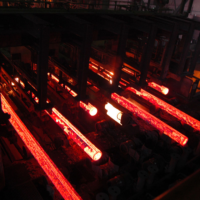
Root Cause Complexity: Billet transverse cracks are rarely caused by a single factor; they typically result from the intersection of deep oscillation (vibration) marks, thermal stress, and micro-alloy precipitation.
The Chemistry Factor: High concentrations of Aluminum (Al), Niobium (Nb), and Vanadium (V) exacerbate crack susceptibility, particularly during peritectic phase transformations.
Thermal Management is Critical: Operating within the steel’s "ductility trough" (typically 700°C–900°C) during bending or unbending significantly increases the risk of transverse surface cracks.
Strategic Mitigation: Permanent resolution requires a balanced approach to mold oscillation tuning, secondary cooling optimization, strict pouring temperature control, and mold taper maintenance.
Table of Contents
Accurate diagnosis begins on the cooling bed. Transverse cracks orient themselves perpendicular to the casting direction. They almost exclusively originate at the base of oscillation marks on the strand surface. These marks act as natural stress concentrators. When thermal or mechanical strain exceeds the high-temperature strength of the solidifying shell, the root of the oscillation mark tears open.
Inspectors must differentiate between superficial micro-cracks and deep sub-surface propagation. Surface-level micro-cracks may only penetrate a few millimeters. They sometimes disappear after light conditioning in the scarfing yard. Deep sub-surface propagation indicates severe thermal stress or embrittlement at the grain boundaries. These deeper fissures often hide beneath a seemingly intact scale layer. You need magnetic particle inspection or macro-etching to fully reveal their depth. Operators frequently misdiagnose these as minor surface blemishes until the billet hits the rolling mill.
Ignoring these casting defects guarantees severe complications during the rolling process. As the billet enters the roughing mill, the compressive and tensile forces of the rolls act upon the existing fissures. Instead of welding shut, oxidized transverse cracks tear further open. The initial casting defect elongates and distorts along the rolling direction.
This evolution translates directly into severe rolling surface defects. Minor transverse cracks transform into scabs and slivers, ruining the surface finish of the final rolled product. In extreme cases, particularly with high-strength low-alloy (HSLA) steels, deep transverse cracks act as initiation sites for catastrophic fractures. This leads to cobbles on the rolling mill. A cobble causes massive production delays, equipment damage, and total loss of the material. You cannot roll your way out of a bad casting practice.
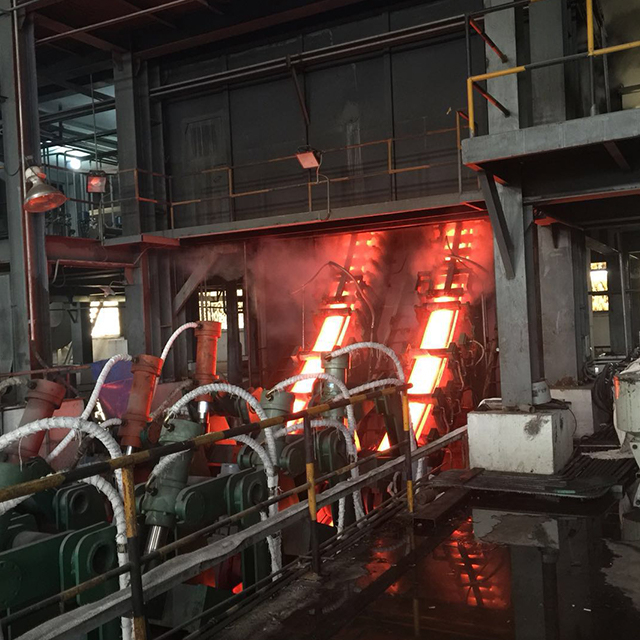
Mold oscillation prevents the solidifying steel shell from sticking to the copper mold tube. Improper oscillation parameters directly cause excessively deep vibration marks. When the negative strip time is too long or the oscillation stroke is too aggressive, the meniscus folds deeply inward. This mechanical folding creates a sharp notch on the billet surface.
These deep notches are the primary initiation sites for billet transverse cracks. The sharp root of a deep oscillation mark multiplies localized stress. As the billet cools and shrinks, longitudinal tensile stresses concentrate at these notches. If the stress exceeds the local yield strength of the hot steel, a crack propagates along the austenite grain boundaries originating from the notch root. We track negative strip time closely; anything exceeding 0.15 seconds on sensitive grades usually spells trouble.
Chemical composition dictates the inherent crack susceptibility of the steel. Micro-alloying elements like Aluminum (Al), Niobium (Nb), and Vanadium (V) increase the final strength of the steel. They also drastically complicate the continuous casting process. As the steel cools through specific temperature ranges, these elements react with carbon and nitrogen.
This reaction causes the precipitation of fine carbonitrides exactly at the austenite grain boundaries. These precipitates pin the grain boundaries. They prevent them from sliding to accommodate thermal strain. The formation of thin, softer ferrite films around these hardened austenite grains concentrates all the strain into the ferrite layer. This metallurgical condition drastically reduces the high-temperature ductility of the steel. It leads directly to intergranular failure and transverse cracking.
Continuous casting relies on controlled, rapid cooling. As liquid steel transitions to a solid shell, it undergoes significant thermal contraction. If heat extraction in the mold or secondary cooling zones is non-uniform, the shell cools at different rates. This uneven cooling generates massive internal thermal stresses.
The superposition of this thermal stress onto the mechanical stress from withdrawal forces creates a highly volatile environment. When one face of the billet shrinks faster than the adjacent face, the resulting bending moment places the surface under severe tension. If this tension occurs while the surface temperature is within a brittle zone, the solidifying shell simply pulls itself apart. You will see this manifest as distinct transverse fissures, often worse on the inner radius of curved casters.
Steel grades containing between 0.09% and 0.17% carbon are notoriously difficult to cast. These peritectic steels undergo a massive phase transformation from delta-ferrite to austenite just below the solidification temperature. This specific crystallographic shift is accompanied by a sudden and severe volume contraction. This contraction often exceeds typical thermal shrinkage.
This massive volume contraction causes the thin solidifying shell to pull away from the copper mold wall prematurely. The resulting air gap destroys heat transfer. The shell reheats, thins out, and loses strength. Specific pouring temperature ranges dictate the severity of this transformation. High tundish superheat exacerbates the unevenness of the shell growth. It drastically increases the severity of crack formation in peritectic grades.
The copper mold tube is the heart of the continuous caster. Its internal geometry must perfectly match the shrinkage profile of the solidifying steel. As the mold tube wears down over hundreds of heats, it loses its designed taper. An improper taper profile fails to compensate for the natural solidification shrinkage of the billet.
When the taper is insufficient, the shrinking steel pulls away from the copper. This creates an insulating air gap. This gap severely retards heat transfer, leading to localized hot spots and a dangerously thin shell. Excessive taper mechanically crushes the solidifying shell. This generates immense friction and longitudinal stress. Both scenarios create the exact localized shell stress required to rip open transverse cracks at the oscillation marks. We recommend measuring mold profiles with an inclinometer every 100 heats.
Stability at the meniscus is non-negotiable for surface quality. Unstable mold levels create irregular oscillation marks and uneven shell growth. Erratic steel flow or faulty level control sensors drive these fluctuations. Every sudden fluctuation in the liquid level leaves a distinct, often deeper, mark on the solid shell.
Mold powder or oil lubrication must perform flawlessly. Improper mold slag viscosity prevents uniform infiltration into the gap between the shell and the copper tube. Poor lubrication increases friction between the descending billet and the oscillating mold. This friction translates directly into longitudinal tensile stress on the fragile shell. It tears the surface open at the weakest points.
Once the billet exits the mold, it enters the secondary cooling zone. The intensity of the water sprays here must be meticulously calibrated against the third ductility trough of the specific steel grade. This trough represents a temperature range where the steel becomes highly embrittled due to phase transformations and precipitate formation. This typically occurs between 700°C and 900°C.
Abnormalities in spray patterns often lead to over-cooling. This happens frequently at the billet corners and edges. If the secondary cooling drives the surface temperature down into this ductility trough just as the billet reaches the unbending rolls, disaster strikes. The mechanical strain of unbending, applied to embrittled steel, guarantees the formation of deep transverse cracks.
Secondary cooling relies entirely on the quality of the water pumped through the system. Poor water quality introduces scale, biological growth, and suspended solids into the cooling circuit. These contaminants rapidly clog the fine orifices of spray nozzles, particularly in air-mist systems. A partially clogged nozzle creates a dry streak down the face of the descending billet.
This dry streak causes the local surface temperature to rebound. The adjacent areas continue to cool rapidly. This massive thermal gradient across the billet face generates severe transverse tensile stress. Scale buildup inside the copper mold tube water jacket acts as a thermal insulator. A mere millimeter of scale can reduce heat transfer efficiency by over twenty percent. This leads to a dangerously thin shell exiting the mold, which is highly prone to bulging and subsequent transverse cracking at the unbending point. Regular water chemistry audits and closed-loop filtration systems are mandatory to maintain uniform heat extraction.
The physical architecture of the continuous caster heavily influences defect generation. Mechanical stresses are primarily introduced by the bending and unbending forces applied to the billet. If these forces are applied while the surface temperature resides within the brittle zone, the steel cannot plastically deform to absorb the strain.
Curved or bow-type casters carry a higher risk profile for transverse cracks. They require a distinct unbending point where strain is concentrated. Vertical casters eliminate this unbending strain, inherently reducing crack susceptibility. Poor alignment of guide rolls, excessive withdrawal roll pressure, or erratic drive speeds introduce sudden mechanical shocks. These shocks easily fracture the hot shell.
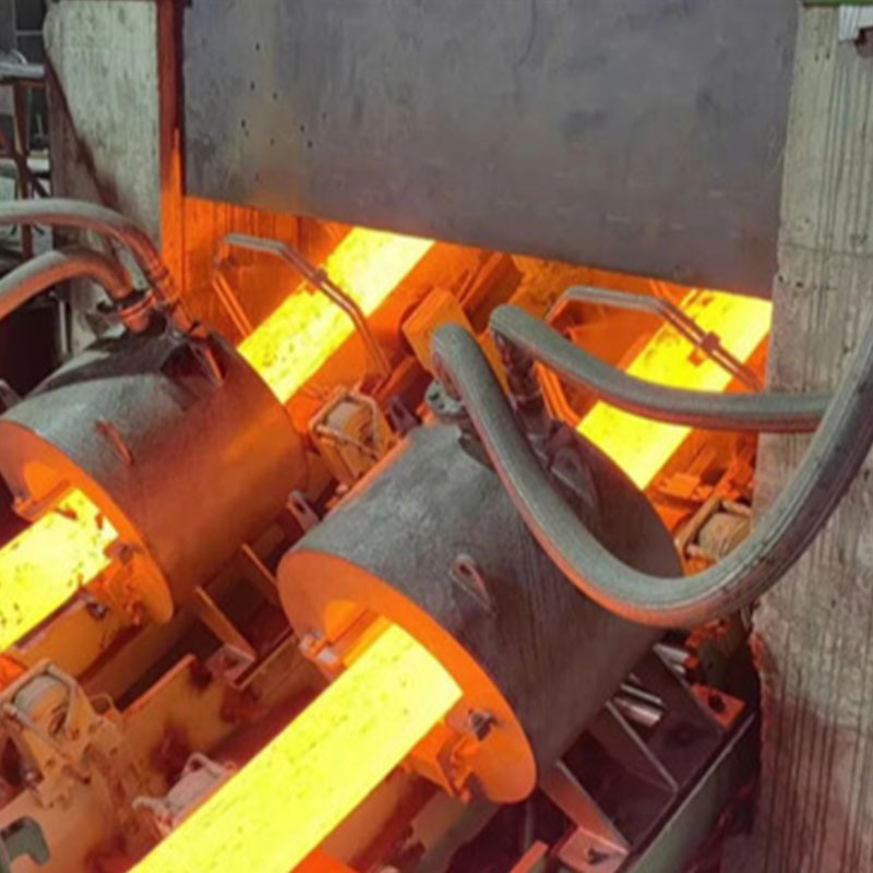
Eliminating deep vibration marks requires recalculating the oscillation dynamics. Plant engineers must implement high-frequency, short-stroke oscillation profiles. A shorter stroke physically reduces the depth of the meniscus fold. A higher frequency ensures adequate lubrication and prevents sticking.
The goal is to minimize the negative strip time while maintaining enough downward velocity to strip the shell from the mold wall. By reducing the depth of the oscillation marks, you neutralize the primary stress concentrators. This single adjustment drastically raises the threshold of mechanical and thermal stress the billet surface can withstand before cracking.
Secondary cooling functions as a metallurgical tool, not just a heat extraction mechanism. Metallurgists must map the specific ductility trough for the steel grade being cast. They must design a cooling profile that avoids this dangerous temperature zone during critical mechanical operations.
Operators choose between hard cooling and soft cooling approaches based on the machine design and steel grade. The objective is to ensure the billet surface temperature remains either safely above the ductility trough (ductile austenite) or safely below it (ductile ferrite) when passing through the unbending rolls. Transitioning to air-mist nozzles provides a wider turndown ratio. This allows for precise surface temperature control without localized over-cooling.
Cooling Strategy Comparison
Strategy Type | Temperature Target at Unbending | Primary Benefit | Associated Risk |
|---|---|---|---|
Hard Cooling | Below 700°C | Pushes steel past the brittle phase transformation before mechanical strain is applied. | High risk of internal halfway cracks due to massive thermal gradients. |
Soft Cooling | Above 900°C | Maintains steel in the highly ductile austenitic phase during unbending. | Risk of bulging between rolls and potential breakouts if the shell is too thin. |
Plateau Cooling | Isothermal hold | Minimizes thermal shock by maintaining a steady surface temperature. | Requires highly advanced, dynamic air-mist spray control systems. |
Chemistry adjustments offer a powerful defense against surface defects. Strict control of the Manganese to Sulfur (Mn/S) ratio is mandatory. Maintaining a ratio above 20 prevents the formation of low-melting-point Iron Sulfide (FeS) films at the grain boundaries. This eliminates hot shortness.
Pouring temperature dictates the solidification structure. High tundish superheat promotes the growth of long columnar grains. These grains are highly susceptible to cracking along their boundaries. Optimizing the superheat to a lower, tightly controlled range promotes equiaxed grain growth. An equiaxed structure distributes strain much more evenly. This significantly improves the high-temperature ductility of the cast billet.
Beyond intentional micro-alloying, tramp elements introduced through scrap steel significantly impact crack susceptibility. Copper (Cu), Tin (Sn), and Antimony (Sb) accumulate in the steel bath because they cannot be oxidized out during the melting process. As the steel solidifies in the continuous caster, these low-melting-point residuals segregate to the austenite grain boundaries.
During secondary cooling, as the surface oxidizes, elements like copper do not oxidize. Instead, they form a liquid copper-rich phase at the steel surface just below the scale layer. This liquid phase penetrates the grain boundaries, causing a phenomenon known as hot shortness. When the billet undergoes the mechanical strain of unbending, these liquid-infiltrated boundaries simply pull apart, forming deep transverse cracks. Controlling scrap quality and diluting high-residual heats with virgin pig iron or direct reduced iron (DRI) is necessary to keep copper equivalent levels below the critical threshold for sensitive grades.
Mechanical precision in the mold is non-negotiable. Plants must establish rigid protocols for the regular inspection and measurement of copper mold tubes. Using advanced profiling tools, maintenance teams track wear patterns. They must discard tubes before they lose their critical internal geometry.
Dynamic adjustment of mold taper is required when switching between steel grades. Peritectic steels require a different taper profile than high-carbon grades due to their distinct shrinkage behaviors. Matching the mold taper precisely to the steel grade's shrinkage profile maintains uniform contact. It ensures even heat transfer and prevents the localized stress that initiates transverse cracks.
Bare copper mold tubes wear rapidly under the intense friction and heat of continuous casting. To extend mold life and maintain the critical taper profile, plants utilize advanced mold coatings. Chromium plating is the industry standard, providing a hard, wear-resistant surface that reduces friction between the solidifying shell and the mold wall.
As the chromium layer wears thin, the underlying copper is exposed. This creates a differential friction zone. The steel shell sticks to the exposed copper while sliding freely over the remaining chromium. This stick-slip action generates massive longitudinal stress spikes, tearing the shell at the oscillation marks. Advanced multi-layer coatings, such as Nickel-Cobalt alloys topped with Chromium, offer superior wear resistance and thermal stability. Monitoring coating thickness through regular maintenance intervals ensures the mold retains its low-friction properties, directly reducing the mechanical stress that initiates transverse cracks.
Production demands frequently push for higher casting speeds to maximize throughput. Increasing speed reduces the residence time in the mold. This results in a thinner, hotter, and weaker shell exiting the mold. This thin shell is highly susceptible to bulging and thermal stress.
The trade-off is stark. Pushing throughput too high drastically increases the strain on the solidifying shell. This reintroduces the exact conditions that cause billet transverse cracks. Plant managers must establish strict maximum casting speeds for crack-sensitive grades. You must prioritize surface quality and yield over raw tonnage.
Resolving persistent defects often forces a choice between capital expenditure and process optimization. Upgrading to hydraulic mold oscillators provides infinite, on-the-fly adjustment of stroke and frequency. This offers superior control over oscillation mark depth. Installing dynamic air-mist cooling systems provides unparalleled thermal control.
These upgrades require significant investment. Plants must evaluate the return on investment by first exhausting all parameter tuning options on their existing mechanical setups. Rigorous calibration of existing mechanical oscillators and precise auditing of water spray nozzles often yield massive improvements without heavy capital spending.
The most sophisticated continuous caster will still produce defective billets if operational consistency is lacking. The human element remains a critical variable. Eliminating transverse cracks requires rigorous, ongoing operator training. Crews must understand the metallurgical reasons behind the parameters they control.
Maintaining this standard requires high quality control overhead. Continuous caster alignment audits must become routine. Implementing real-time defect monitoring systems and thermal imaging cameras adds complexity to the operation. It is absolutely necessary to catch thermal abnormalities before they manifest as scrapped material.
When an outbreak of transverse cracking occurs, operators should follow a strict diagnostic sequence:
Verify the tundish superheat is within the specified 15°C to 25°C target range for the active steel grade.
Inspect the secondary cooling zone for clogged nozzles, misaligned spray headers, or incorrect water pressure settings.
Measure the copper mold tube taper using a digital inclinometer to confirm it matches the required profile for the current carbon equivalent.
Analyze the oscillation marks on the affected billets to determine if negative strip time has drifted out of specification.
Review the chemical analysis of the heat, specifically checking the Mn/S ratio and the concentration of micro-alloying elements like Niobium and Vanadium.
Conduct a mechanical alignment check of the unbending rolls to ensure no excessive strain is being applied to the strand.
To permanently resolve billet transverse cracks and stabilize your continuous casting operation, execute the following actions immediately:
Initiate a comprehensive caster alignment audit, focusing specifically on the unbending rolls and withdrawal drive synchronization.
Review current secondary cooling curves against the specific ductility trough of your most problematic steel grades and adjust spray flows accordingly.
Implement a strict inspection schedule for copper mold tubes to ensure taper profiles remain within design tolerances before every sequence.
Consult with metallurgical engineers to transition toward high-frequency, short-stroke oscillation profiles to minimize vibration mark depth.
WUXI LIWEI METALLURGY EQUIPMENT CO., LTD specializes in metallurgical engineering design, equipment manufacturing, installation, and commissioning, with integrated capabilities covering steel melting, continuous casting machines (CCM), and rolling mill projects.
Backed by engineering and practical project experience, the company can support steel plants in improving continuous casting equipment, process stability, billet quality, and overall production efficiency.
A: The primary cause is the intersection of deep oscillation marks acting as stress concentrators, combined with severe thermal and mechanical stress applied while the steel's surface temperature is within its brittle ductility trough.
A: Improper mold oscillation creates deep vibration marks. The sharp root of these marks acts as a localized stress multiplier. When longitudinal thermal or mechanical tension is applied, the shell tears open precisely at these deep notches.
A: Peritectic steels undergo a massive volume shrinkage during the delta-ferrite to austenite phase transformation. This sudden contraction creates uneven shell growth, air gaps in the mold, and massive localized thermal stress, making the shell highly susceptible to cracking.
A: These micro-alloying elements precipitate as fine carbonitrides at the austenite grain boundaries as the steel cools. This precipitation pins the boundaries, preventing them from sliding to absorb strain, thereby severely reducing the steel's high-temperature ductility.
A: It is a specific temperature range, typically between 700°C and 900°C, where the steel undergoes phase transformations and precipitation. This makes the solidifying shell highly embrittled and susceptible to cracking under mechanical strain during unbending.
A: Yes. By modifying secondary cooling rates, operators can ensure the billet's surface temperature remains either safely above or safely below the brittle ductility trough when the steel passes through the unbending rolls, avoiding strain during the brittle phase.


